
1. Introduction and Research Background
The global manufacturing industry is undergoing a transformative shift driven by the emergence of intelligent manufacturing and digital production technologies. Among these, 3D printing, also known as additive manufacturing, has been recognized as a pivotal technology for the new industrial revolution. Traditional manufacturing methods, particularly in the casting sector, exhibit significant sensitivity to part complexity, often requiring elaborate tooling, lengthy lead times, and substantial upfront investment for complex components. In contrast, 3d sand printing technology offers a paradigm shift, presenting minimal sensitivity to geometric complexity, thus enabling the rapid production of intricate molds and cores directly from digital models without the constraints of traditional pattern-making.
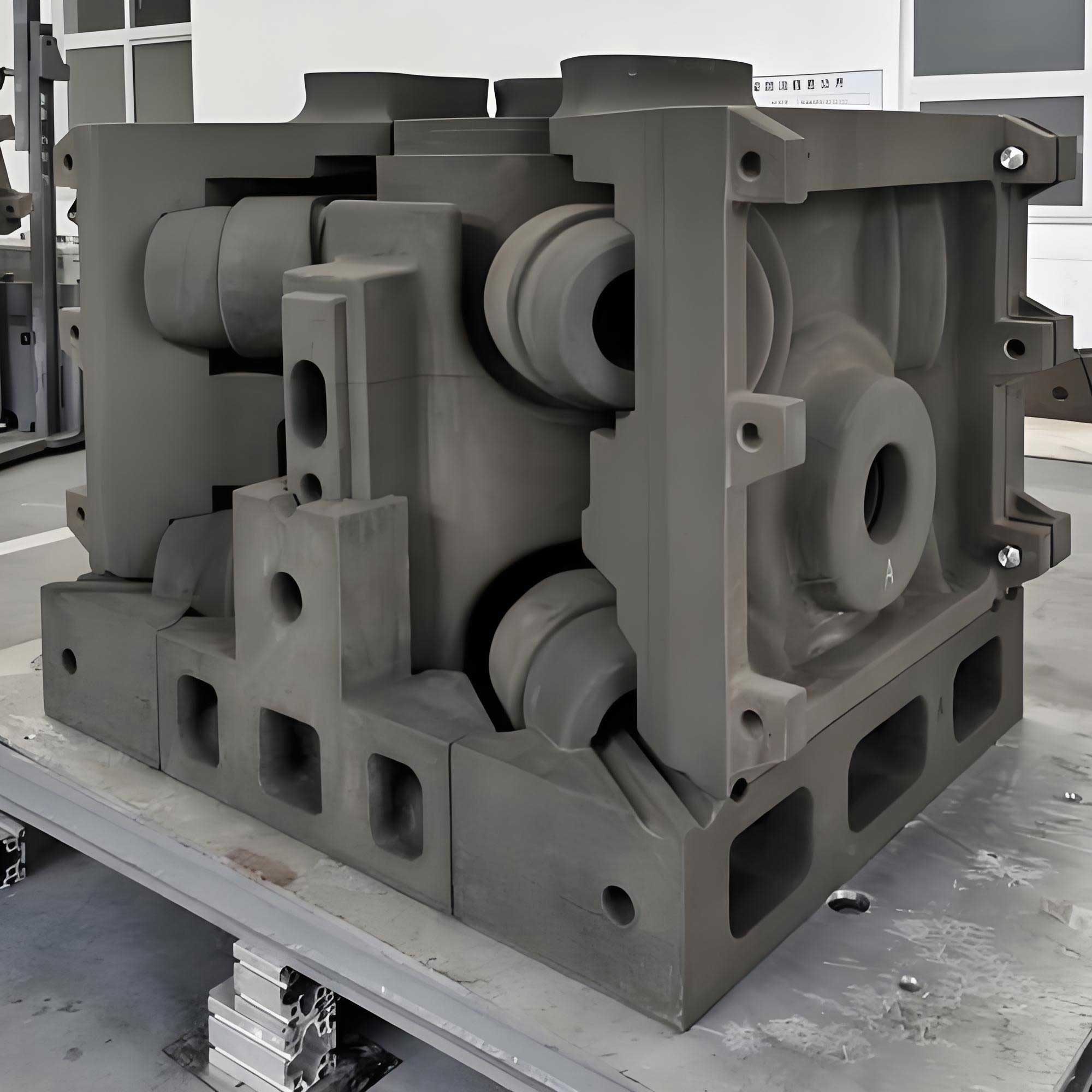
By integrating the design freedom of 3d sand printing with the maturity and cost-effectiveness of conventional sand casting, a novel manufacturing paradigm emerges. This hybrid approach, often termed 3D sand printing rapid casting, allows for the direct fabrication of sand molds, eliminating the need for physical patterns and core boxes. This is particularly advantageous for low-volume production, prototype development, and the manufacturing of high-complexity, high-value-added components such as engine cylinder blocks. The technology is capable of creating conformal gating systems, complex internal cooling channels, and optimized riser placements, which are either impossible or highly impractical to achieve with conventional molding processes. The research presented in this thesis focuses on the holistic study of this technology, covering process parameter optimization, numerical simulation of the casting process, and the subsequent rapid casting trial of an automotive engine cylinder block to validate the entire process chain.
The automotive industry, in particular, is under immense pressure to achieve lightweighting goals to improve fuel efficiency and reduce emissions. Aluminum alloys, especially the A356 (ZL101A) family, have emerged as preferred materials for replacing heavier cast iron components. However, casting aluminum alloy components like engine cylinder blocks presents unique challenges, including high susceptibility to porosity, oxide inclusions, and shrinkage defects. The success of such castings heavily relies on the gating system design, pouring parameters, and mold characteristics. This research addresses these challenges by leveraging the unique capabilities of 3d sand printing to design and fabricate an optimized casting system for a complex engine cylinder block, followed by rigorous simulation to verify the process before conducting a physical trial production.
2. Materials and Experimental Procedures
2.1 Materials
The material chosen for the research was the ZL101A (AlSi7Mg0.3) aluminum alloy, a standard casting alloy known for its good castability, corrosion resistance, and excellent mechanical properties after T6 heat treatment. The standard composition is given in Table 1. The actual melt composition, treated with strontium for silicon modification, is detailed in Table 2.
Table 1: Standard composition of ZL101A alloy (wt. %)
| Element | Si | Mg | Ti | Al |
| Content | 6.5-7.5 | 0.25-0.45 | 0.08-0.20 | Balance |
Table 2: Actual melt composition of casting aluminum alloy (wt. %)
| Element | Si | Mg | Ti | Sr | Fe | Zn | V | Al |
| Content | 7.223 | 0.322 | 0.106 | 0.041 | 0.109 | 0.017 | 0.015 | Balance |
2.2 Sand Mold 3D Printing Equipment and Materials
The sand molds for both the initial parameter study and the final cylinder block casting were fabricated using a custom-developed PCM-800 3D sand printing system. The printer operates on the principle of binder jetting, using a print-head to selectively deposit a furan resin binder onto a pre-spread layer of sand. Key equipment parameters are listed in Table 3.
Table 3: Main parameters of the PCM-800 3D sand printer
| Parameter | Value |
| Max Print Size (mm) | 800 × 750 × 500 |
| Layer Thickness (mm) | 0.2 – 0.5 |
| Printing Speed | 25 s/layer |
| Dimensional Accuracy (mm) | ±0.3 |
The primary sand material used was a high-purity silica sand with an angular to sub-spherical particle morphology. The binder system was a two-part system consisting of a furan resin (2.36 wt% of sand) and a sulfonic acid-based catalyst (0.4 wt% of sand). To evaluate the performance of the printed sand, standard test specimens were printed and tested according to industry standards. The results, shown in Table 4, confirmed that the mechanical and physical properties of the 3d sand printing molds were suitable for use in gravity casting.
Table 4: Test results of 3D printed sand standard samples
| Property | Tensile Strength (MPa) | Compressive Strength (MPa) | Bending Strength (MPa) | Permeability | Gas Evolution (ml/g) |
| Value | 0.8 – 1.5 | > 2.0 | 1 – 2.5 | 80 – 120 | 12 – 14 |
2.3 Melting and Heat Treatment
The ZL101A alloy was melted in an induction furnace. After complete melting at 740°C, a degassing and refining process was carried out using a rotary impeller degasser with argon gas. Strontium was added for eutectic silicon modification. After refining and modification, the melt was held at the pouring temperature (700°C – 740°C) for 30 minutes to ensure homogeneity and allow inclusions to float out. Following casting, the test specimens and cast components underwent a standard T6 heat treatment consisting of: (1) solution heat treatment at 530°C for 8-12 hours; (2) quenching in warm water (70°C); and (3) artificial aging at 180°C for 6-8 hours.
3. Results and Discussion: Process Parameter Optimization
Before the full-scale implementation of 3d sand printing for the cylinder block, a comprehensive study was conducted to understand how various process parameters influence the final properties of the cast aluminum alloy. Coupons with a wall thickness of 30 mm were cast using molds produced by 3d sand printing, and the results were compared against those from traditional sand molds and permanent metal molds. This initial study was crucial for establishing a baseline of mechanical properties and microstructural characteristics achievable with the 3D printed molds.
3.1 Effect of Mold Type on Casting Quality
In this comparison, three different mold types were used to cast identical ZL101A test coupons: (1) a conventional clay-bonded sand mold; (2) a mold produced via 3d sand printing; and (3) a standard permanent metal mold. The pouring temperature was 720°C. The microstructures of the resultant castings are shown in Figure 1.
Figure 1 (Illustrative). Microstructure of casting samples from different molds: (a, b) conventional sand mold; (c, d) 3D printed sand mold; (e, f) permanent metal mold.
The microstructures obtained under different mold conditions highlight the distinct cooling rates and solidification behavior. The secondary dendrite arm spacing (SDAS) was measured using the linear intercept method, as per Equation (1):
$$d = \frac{1}{m} \sum_{i=1}^{m} \frac{l_i}{n_i – 1} \tag{1}$$
where \(d\) is the SDAS (μm), \(l_i\) is the intercept length (μm), \(n_i\) is the number of dendritic arm intercepts, and \(m\) is the total number of measured groups.
The casting from the permanent metal mold exhibited the finest microstructure with SDAS of 25.94 μm, due to the rapid heat extraction provided by the metallic mold. The casting from the 3d sand printing mold (SDAS of 84.08 μm) had a coarser microstructure than the traditional sand mold (SDAS of 63.05 μm), which can be attributed to the inherently different thermal properties and densities of the molds. Despite the slightly coarser structure, the 3D printed sand mold casting displayed a more uniform and defect-free microstructure, with fewer inclusions and porosity, compared to the conventional sand mold casting. This indicates a high level of process control and consistency inherent to the 3D printing process.
The mechanical properties of the castings produced in these different molds are summarized in Table 5. The 3D printed sand mold casting exhibited a better combination of tensile strength and elongation (131 MPa, 2.2%) compared to the conventional sand mold casting (127 MPa, 1.9%). The increased ductility of the 3D printed sand mold casting suggests a lower concentration of stress-risers, such as oxide inclusions and porosity. SEM fracture surface analysis confirmed a mixed-mode fracture (quasi-cleavage and dimple) in the 3D printed sand mold casting, whereas the conventional sand mold casting exhibited a more brittle cleavage fracture.
Table 5: Comparison of mechanical properties and density of samples from different molds
| Mold Type | Tensile Strength (MPa) | Elongation (%) | Density (g/cm³) |
| Traditional Sand Mold | 127 ± 3 | 1.9 ± 0.2 | 2.6260 |
| 3D Printed Sand Mold | 131 ± 2 | 2.2 ± 0.3 | 2.6300 |
| Permanent Metal Mold | 184 ± 5 | 3.4 ± 0.4 | 2.6753 |
3.2 Effect of Pouring Temperature and Mold Preheating
Pouring temperature is a critical parameter that significantly affects melt fluidity, solidification rate, and the soundness of the final casting. To study this, molds from 3d sand printing were baked to remove volatiles and then cooled to room temperature. ZL101A melt was poured at varying temperatures: 700°C, 710°C, 720°C, and 740°C. The mechanical properties of the T6 heat-treated samples are shown in Table 6 and demonstrate an optimal pouring temperature of around 720°C. At this temperature, complete eutectic modification occurred, resulting in fine, spheroidal silicon particles and a uniform, fine-grained α-Al matrix. Lower pouring temperatures (700°C, 710°C) led to partial modification and plate-like silicon, while higher temperatures (740°C) led to coarsening of the silicon phases and the precipitation of Fe-rich intermetallic phases, as confirmed by energy dispersive spectroscopy (EDS).
Table 6: Effect of pouring temperature on T6 properties of cast samples from 3D printed sand molds
| Pouring Temperature (°C) | Tensile Strength (MPa) | Elongation (%) | SDAS (μm) |
| 700 | 195 ± 5 | 0.3 | 98.55 |
| 710 | 208 ± 4 | 0.4 | 90.62 |
| 720 | 229 ± 3 | 0.5 | 70.69 |
| 740 | 215 ± 6 | 0.3 | 85.47 |
In a separate set of experiments, the influence of preheating the 3D printed sand mold before pouring was investigated. Molds were heated to 100, 150, 200°C, while the pouring temperature was maintained at 720°C. The results (Table 7) showed a clear trend: preheating the molds reduced the mechanical properties of the castings. For instance, increasing the preheat temperature from ambient (no preheat) to 200°C caused a decrease in tensile strength from 218 MPa to 205 MPa. This is because a preheated mold reduces the cooling rate of the melt, leading to a coarser dendritic structure and the formation of large secondary phases. Since the 3D printed sand molds were effectively dried, no preheating was necessary for degassing purposes, making the room-temperature pouring process the most effective choice for optimizing properties and production efficiency.
Table 7: Effect of mold preheat temperature on T6 properties of cast samples from 3D printed sand molds
| Preheat Temp. (°C) | Tensile Strength (MPa) | Elongation (%) | SDAS (μm) |
| Ambient | 218 ± 4 | 0.4 | 57.58 |
| 100 | 212 ± 5 | 0.4 | 68.53 |
| 150 | 209 ± 3 | 0.3 | 75.10 |
| 200 | 205 ± 6 | 0.3 | 90.72 |
3.3 Effect of Printing Layer Thickness
The printing layer thickness is a defining parameter of the 3d sand printing process, as it directly influences the amount of binder used and the surface quality of the mold. Test molds were printed with layer thicknesses of 0.4mm and 0.5mm. The results of this comparison are presented in Table 8. The casting produced from the 0.5mm layer mold exhibited superior mechanical properties (229 MPa tensile strength, 0.5% elongation) and a higher density (2.6503 g/cm³) compared to the casting from the 0.4mm layer mold (218 MPa, 0.4%, 2.6454 g/cm³). The thinner layer mold, having 25% more layers, contains a higher total volume of binder. During pouring, the higher binder content leads to greater gas evolution, causing increased porosity and defects within the casting. From both a performance and an economic perspective, a 0.5mm layer thickness was identified as the preferred parameter for this application, effectively balancing mold strength with minimizing volumetric binder content.
Table 8: Effect of mold printing layer thickness on casting properties (T6)
| Layer Thickness (mm) | Tensile Strength (MPa) | Elongation (%) | Density (g/cm³) |
| 0.4 | 218 ± 4 | 0.4 | 2.6454 |
| 0.5 | 229 ± 3 | 0.5 | 2.6503 |
4. Gating System Design and Simulation of the Cylinder Block
4.1 Component Analysis
The objective component for this research was a modern three-cylinder, direct-injection automotive engine cylinder block. The primary characteristic of this component is its complexity. The overall dimensions of the casting blank are approximately 500 × 500 × 500 mm, with a total weight of 18.10 kg. The wall thickness is highly variable, ranging from 2 mm (between the cylinder liners) to 40 mm (at the main bearing supports). To enhance wear resistance and overall durability, three cast-iron cylinder liners (Figure 2) with an outer diameter of 87.6 mm and wall thickness of 6 mm are integrated into the aluminum alloy body. The successful casting of this component requires meticulous attention to the gating system, the placement of chills, and the thermal management of the cylinder liners.
4.2 Design of the Conformal Gating System
The design flexibility offered by 3d sand printing enabled the creation of a conformal, stepped gating system, a significant departure from conventional designs. The design allows for a smooth, layered filling of the mold cavity, minimizing turbulence and oxidation. The design of the gating ratio followed the principles of the “large orifice outflow” theory for gravity casting, as shown in Equation (2):
$$A_{direct} : A_{cross} : A_{inner} = 1 : (2 \sim 4) : (2 \sim 4) \tag{2}$$
The cross-sectional area of the inner gate (\(A_{inner}\)) was calculated using Equation (3):
$$A_{inner} = \frac{G_L}{\rho_L \mu t \sqrt{2gh_p}} \tag{3}$$
where \(G_L\) is the mass of the melt flowing through the system (kg), \(\rho_L\) is the density of the melt (kg/m³), \(\mu\) is the flow loss coefficient, \(t\) is the pouring time (s), \(g\) is the acceleration due to gravity (m/s²), and \(h_p\) is the mean static pressure head (m).
Based on these calculations, a 60 mm diameter sprue was selected to ensure sufficient and smooth filling. Three different casting orientations (A, B, and C) were designed to evaluate their impact on casting quality. A comparative overview of these schemes is provided in Table 9.
Table 9: Comparison of three different casting process designs for the cylinder block
| Design | A – Upright | B – Sideway | C – Inverted |
| Fill Location | Bottom / Thick sections | Bottom / Thick sections | Top / Cylinder liners |
| Total Mass /kg | 46.99 | 40.86 | 48.17 |
| Yield /% | 38.52 | 44.30 | 37.58 |
| Design Merits | Reduced initial turbulence | High yield | Good fusion with liners |
Additional auxiliary process features were designed for the gating system, leveraging the freedom of 3D geometry in the sand mold. These included strategically placed chills to eliminate hot spots, integrated heat sinks and vent holes to manage gas and heat extraction effectively, and a preheating system to regulate the temperature of the cast-iron cylinder liners, ensuring a strong metallurgical bond between the liner and the aluminum casting.
4.3 Simulation Setup
The designed casting process was ratified and optimized using the ProCAST casting simulation software. The 3D geometry of the casting, gating system, chills, and sand mold was imported into ProCAST. A finite-element mesh was generated using a graded tetrahedral mesh strategy. The component mesh size was set to 4 mm, while the sand mold exterior was meshed at a coarse 20 mm to reduce computation time. The total number of volume elements was 11,717,789.
The boundary conditions and material properties for the simulation were set as follows, according to the findings of the initial process parameter study: the casting was ZL101A at a pouring temperature of 730°C; the interface heat transfer coefficient between the casting and the sand mold was set to 500 W/(m²·°C); the coefficient between the casting and the cast-iron chills/liners was set to 2000 W/(m²·°C). A critical feature of the process was the preheating of the cast-iron cylinder liners to 400°C using built-in heating rods to promote a sound metallurgical bond. The initial temperature for the chills was set to ambient temperature. The mass flow rate during pouring was calculated using Equation (4):
$$Mass Flow Rate = \frac{Volume \times Fill Limit \times Density}{Fill Time} \tag{4}$$
Based on the component volume and a designated fill time of 16 seconds, the mass flow rate was set to 2.93 kg/s.
4.4 Simulation Results and Analysis
The simulation results for the three different filling systems were analyzed from several perspectives: flow behavior, temperature field, and defect formation. The comparison of filling efficiency and solidification patterns is summarized in Table 10.
Table 10: Comparison of simulation results for various casting process designs
| Criteria | Design A | Design B | Design C |
| Filling Quality | Good, stable | Turbulence in early stages | Excellent, efficient |
| Solidification Uniformity | Good | Poor, isolated liquid zones | Excellent, sequential |
| Total Shrinkage Porosity (cc) | 0.913 | 1.043 | 0.899 |
| Key Defect Locations | Some minor porosity | Large defect in assembly holes | Defects in non-critical areas |
| Overall Performance | Acceptable | Unacceptable | High Quality |
The simulation revealed that Design C, which involved pouring the metal with the cylinder liners positioned in the lower part of the mold, provided the most favorable results. This design allowed the hot melt to fill the casting cavity efficiently, coming into direct contact with the preheated cylinder liners, thereby ensuring excellent fusion and minimizing the risk of cold shuts or incomplete bonding. The overall filling time for the casting body was calculated to be 10.67 seconds, and the total volume of defects was only 0.899 cc. This simulated defect volume, primarily located in non-critical areas, confirmed the robustness of the design. Design B was deemed unsuitable due to a large, concentrated shrinkage defect predicted in a critical mounting area.
5. Rapid Casting Trial of the Engine Cylinder Block
5.1 Mold Printing and Preparation
Based on the optimal process parameters determined from the parameter study and the validated gating design from the simulation, the sand molds for the engine cylinder block were manufactured. The entire mold system was designed as a single unit where possible and then partitioned into manageable segments to facilitate the placement of internal chills, core assemblies, and heating elements. The digital models were sliced with a layer thickness of 0.5 mm, and the printing parameters included a printing speed of 25 s/layer, resulting in a total printing time of 10 hours for the complete set of molds.
After the printing process, the molds were removed from the print bed and residual, unbonded sand was cleaned away. A zircon-based refractory coating was applied to the mold cavities to improve surface finish and prevent metal penetration. The coated molds were then oven-dried at 150°C for 2 hours to remove residual moisture and binder volatiles, a critical step for minimizing gas defects. Following drying, the pre-fabricated cast-iron cylinder liners were installed into the mold, positioned over their respective heating rods. The built-in heating rods were then used to preheat the liners to 400°C.
5.2 Pouring and Post-Processing
The ZL101A alloy was melted and prepared as per the procedures described in Section 2.3, with a pouring temperature of 730°C. The pour was executed, and the mold was allowed to cool for 10 minutes. The casting was then de-molded, revealing a complete and well-formed cylinder block. After the removal of the gating system and risers, the casting was subjected to the T6 heat treatment process.
5.3 Evaluation of the Trial Casting
The quality and reliability of the cast engine cylinder block were evaluated using a systematic set of inspection methods. The results confirmed the effectiveness of the 3D sand printing-based casting process and its suitability for mass production of complex automotive components.
5.3.1 Macroscopic Inspection and X-ray Analysis
Visual inspection of the cast component confirmed that its external surface was smooth and free from any apparent surface defects such as misruns or cold shuts. The dimensional accuracy of the casting conformed to CT7 (Coarse Tolerance 7) grade, which represents a good level of accuracy for complex sand castings. This precision is a direct benefit of the high fidelity of the 3d sand printing process, and it eliminates the variations often seen in manually assembled sand molds.
X-ray inspection (X-ray radiography) was conducted on the entire casting to assess its internal soundness. The X-ray images from critical zones, including the assembly holes, cooling water jackets, and the main shaft area, confirmed that there were no significant internal defects, such as pores, inclusions, or shrink cavities. The high quality of the internal structure is a testament to the effectiveness of the design process, the optimized gating system, and the absence of binder-related gas defects.
5.3.2 Evaluation of the Cylinder Liner Fusion
To assess the metallurgical bond between the cast-iron liners and the aluminum alloy, the cylinder block was sectioned for macroscopic and microscopic analysis. The cross-sections revealed a robust and continuous interface between the liner and the cast aluminum. Metallographic inspection of the bonding zone showed that the aluminum alloy had successfully penetrated and wetted the prepared surface of the cast-iron liner, predominantly in the region of the liner’s “mushroom” anchors. The measured depth of the aluminum-iron intermetallic fusion layer was consistently in the range of 2-3 mm, with the outer diameter of the post-cast cylinder liner measuring 85.67 mm. This value was within the specified tolerance (≥ 83 mm) and confirms the liners did not distort significantly during casting. The preheating of the liner to 400°C proved critical in ensuring a robust, high-quality bond, which is essential for the engine’s thermal conductivity and durability.
5.3.3 Microstructure and Mechanical Properties
Metallographic analysis of samples taken from the final cylinder block casting showed a uniform and fine microstructure. The α-Al matrix was largely free of element segregation, and the eutectic silicon particles, after T6 heat treatment, appeared highly refined, predominantly in a short back-shaped and spheroidal form. This desirable microstructure was achieved through a combination of Sr modification, controlled solidification rate, and the effective solutionizing step of the T6 treatment.
Tensile test bars, which were cast integrally with the cylinder block, underwent the same T6 heat treatment cycle as the block. The mechanical properties obtained for the trial-produced cylinder block are presented in Figure 3 and Table 11, where they are compared against the standard requirements for a typical automotive-grade ZL101A casting. The concrete achievements substantiate the value of the 3d sand printing approach.
Table 11: Comparison of mechanical properties for test and standard
| Property | Tensile Strength (MPa) | Elongation (%) | Hardness (HB) |
| Standard Requirement | ≥ 220 | ≥ 2.0 | ≥ 80 |
| Test Result | 278 | 2.3 | 97 |
The mechanical test results confirm that the casting not only meets but significantly exceeds the standard mechanical requirements. The yield strength of 278 MPa and elongation of 2.3% highlight the integrity and reliability of the casting, which is a direct function of the sound microstructure and lack of detrimental defects. In addition to mechanical testing, a pressure leak test was performed on the casting. The casting was sealed and subjected to an internal pressure of 0.3 MPa for 5-10 minutes in a water bath. The absence of air bubbles during the test indicated that the casting was leak-tight, confirming that no micro-porosity networks were present in the casting walls.
6. Conclusion
This research conducted a comprehensive study on the application of 3d sand printing technology for the rapid casting of complex aluminum alloy components, with a specific focus on optimizing process parameters and validating a casting process for an automotive engine cylinder block. The following conclusions can be drawn from this work:
(1) The study successfully established that castings produced using molds fabricated via 3d sand printing perform comparably to, or better than, those from traditional sand molds. The 3D printed sand mold castings exhibited better structural integrity with fewer inclusions and porosity, resulting in a superior combination of tensile strength and elongation (131 MPa, 2.2% in as-cast condition compared to 127 MPa, 1.9% for traditional sand molds).
(2) Process parameter optimization determined that for the ZL101A alloy, a pouring temperature of 720°C is optimal when using 3D printed sand molds. The print layer thickness also plays a significant role, with a 0.5 mm layer producing higher-quality castings (density 2.6503 g/cm³) with higher mechanical properties (229 MPa tensile strength after T6) compared to a 0.4 mm layer. Preheating the 3D printed molds was not necessary for achieving high casting quality, as it led to coarsening of the microstructure and a decrease in mechanical properties. After T6 treatment, the cast samples from the optimized 3D printing process achieved a tensile strength of 229 MPa and an elongation of 0.5%.
(3) The design and simulation of the gating system for the engine cylinder block demonstrated the significant advantages of a conformal gating design enabled by 3d sand printing. The simulation was an indispensable tool in validating the casting design, with the most effective orientation being with the cylinder liners at the bottom, heated to a temperature of 400°C. This configuration ensured efficient, uniform filling, and a sound casting. The optimized design simulated a total defect volume of only 0.899 cc and a complete fill time of 10.67 seconds, without defects in critical regions.
(4) The comprehensive process chain, integrating 3d sand printing with optimized casting parameters, was successfully validated through the trial production of the engine cylinder block. The production cycle time from design to casting was reduced to a remarkable 3-4 days, highlighting the rapid-response capability of the technology. The resultant cylinder block met all quality standards, including internal soundness, dimensional accuracy (CT7 grade), excellent bonding with the cast-iron cylinder liners, and a high pressure-tightness. The successful trial production of the cylinder block unequivocally demonstrates that 3d sand printing is a highly viable and superior technology for the cost-effective, rapid, and reliable production of complex, high-value casting components for the automotive and aerospace industries.