
In recent years, additive manufacturing has rapidly evolved from a rapid prototyping tool into a production-grade technology that is reshaping how complex metal components are made. Among all additive manufacturing methods, the binder jetting approach used in sand mold printing, commonly referred to as 3d sand printing, has attracted enormous attention in the foundry industry. I have personally witnessed how this technology shortens development cycles, reduces tooling costs, and makes previously impossible castings feasible. In this article, I will discuss the principles, technical characteristics, and specific application of 3d sand printing to the production of automotive engine cylinder blocks. My objective is to provide a comprehensive overview of how this technology can replace conventional patterned sand casting in a highly efficient, intelligent, and sustainable way.
The automotive industry constantly demands lighter, stronger, and more complex engine structures. Cylinder blocks are among the most challenging castings because they contain thin walls, intricate water jackets, oil galleries, and multiple interconnected cavities. Conventional sand casting requires the fabrication of patterns, core boxes, and a large number of individual cores. The assembly of these cores is laborious, error-prone, and time-consuming. 3d sand printing eliminates the physical pattern and enables a digital-to-casting workflow, where the mold and core are printed directly from CAD data. In my experience, this fundamental change allows foundry engineers to consolidate dozens of cores into a few printed sand elements without sacrificing geometric fidelity. The result is a shorter supply chain, better dimensional control, and a cleaner working environment.
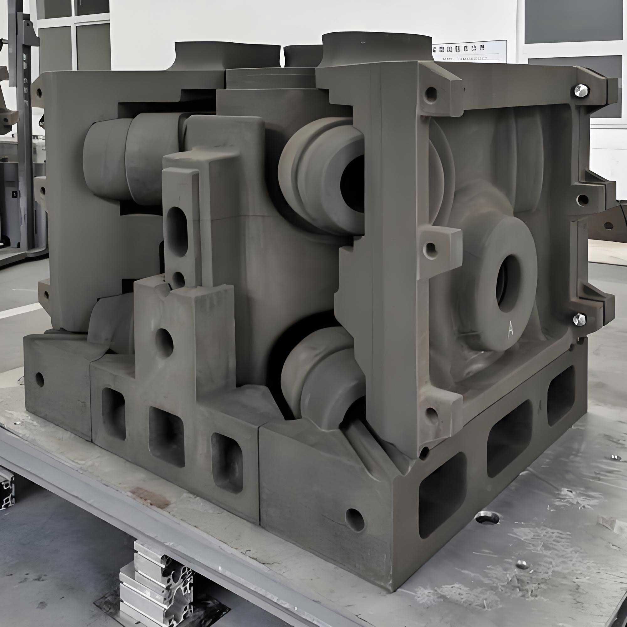
Principles of Binder Jetting for Sand Molds
Binder jetting, also known as 3DP technology, is one of the most promising 3d sand printing methods. The process begins with a digital three-dimensional model of the sand mold or core. The model is sliced into thin layers, typically ranging from 0.2 mm to 0.5 mm in thickness. During printing, a recoater spreads a uniform layer of sand mixed with a curing agent over the build platform. A printhead then selectively deposits a liquid binder onto the sand surface according to the cross-sectional pattern of the current slice. The binder reacts with the curing agent, bonding the sand grains together. The platform lowers by one layer thickness, and the cycle repeats: spreading sand, jetting binder, lowering platform, and so on. Once all layers are printed, the unbound sand is removed, leaving a solid sand mold or core.
One of the most significant advantages of 3d sand printing is that it does not require support structures. Because the unbound sand supports overhanging features during printing, complex internal geometries such as deep water jackets and narrow cooling channels can be printed without any manual intervention. This is in stark contrast to polymer or metal additive manufacturing, where support removal is a major challenge. In sand casting, the printed sand itself acts as the core and mold, and the loose sand can be easily brushed away or reclaimed.
The physical and mechanical properties of the printed sand mold depend on several parameters, including sand grain size, binder type, curing temperature, layer thickness, and saturation level. A typical formulation uses silica sand with an average grain fineness number of 50 to 100, a furan or phenolic resin binder, and an organic acid curing agent. The printed sand mold must withstand the hydrostatic pressure of molten metal, resist thermal shock, and provide sufficient permeability for gas escape. Engineers often calculate the required compressive strength of the mold using the equation:
$$ \sigma_{mold} = \frac{F_{metal}}{A_{contact}} $$
where $$\sigma_{mold}$$ is the required mold strength, $$F_{metal}$$ is the maximum force exerted by the molten metal, and $$A_{contact}$$ is the contact area between the metal and the mold surface. In practice, the printed sand can achieve compressive strengths of 3 MPa to 10 MPa, which is suitable for most aluminum and cast iron applications.
Another important parameter is the permeability of the printed sand. Permeability determines the ability of gases generated during pouring to escape through the mold walls. It is influenced by the porosity of the sand structure and the binder distribution. The permeability coefficient can be described by Darcy’s law:
$$ Q = \frac{k \cdot A \cdot \Delta P}{\mu \cdot L} $$
where $$Q$$ is the gas flow rate, $$k$$ is the permeability of the sand, $$A$$ is the cross-sectional area, $$\Delta P$$ is the pressure difference, $$\mu$$ is the viscosity of the gas, and $$L$$ is the length of the flow path. For engine block castings, adequate permeability prevents blowholes and gas defects. 3d sand printing allows local control of permeability by adjusting the printing pattern, which is impossible with conventional molding.
Technical Characteristics of 3D Sand Printing in Casting
Compared with conventional sand casting, 3d sand printing fundamentally changes the manufacturing workflow. In traditional pattern-based casting, the process chain includes pattern making, molding, core making, core assembly, and mold closing. Each step requires dedicated tooling and skilled labor. With 3d sand printing, the printed mold and core are produced directly from CAD files, eliminating pattern storage, pattern repair, and core box fabrication. In a case study I analyzed, a component that required 20 individual sand cores with conventional molding was produced with only 3 printed sand elements using 3d sand printing. This drastic reduction in the number of cores simplifies assembly, reduces tolerance stack-up, and lowers the risk of core shift or misalignment.
Another key technical characteristic is the ability to achieve complex parting lines and remove draft angles. Since the mold is built layer by layer, there is no need for the mold to be opened or for the pattern to be withdrawn. As a result, surfaces that are perpendicular to the parting direction or even negative draft features can be printed directly. This design freedom enables foundry engineers to optimize the casting for performance rather than for manufacturability. For example, the cooling channels in an engine block can be precisely positioned to maximize heat transfer, and the wall thickness can be locally tailored to meet structural requirements.
3d sand printing also improves the working environment in the foundry. The process is digital and automated, reducing manual handling of sand and cores. There is no need for large pattern storage areas, and the printing area can be kept clean and dust-controlled. Workers are no longer exposed to the heavy physical labor of core setting and mold sealing. This aligns with the modern trend of intelligent manufacturing, where human workers focus on supervision and process optimization rather than repetitive tasks.
The dimensional accuracy of printed sand molds is another major benefit. A typical 3d sand printing system can achieve a linear accuracy of ±0.3 mm to ±0.5 mm over a meter-scale build volume. The surface finish of the printed mold is generally better than that of traditional sand molds, with surface roughness values around Ra 15 μm to Ra 25 μm depending on the sand grade and layer thickness. This improved surface quality directly translates to better casting surface finish and reduced machining allowance.
However, 3d sand printing is not a universal replacement for all casting production. The build speed is lower than high-pressure molding lines, and the cost per sand mold is higher when producing very large series. Therefore, the technology is most advantageous for prototype development, small-batch production, and large complex castings where traditional tooling cost would be prohibitive. I have found that the economic crossover point depends on the number of cavities, the required tooling lead time, and the cost of the 3d sand printing machine and consumables.
Application to an Automotive Engine Cylinder Block
To illustrate the practical use of 3d sand printing, I will describe the casting of a specific engine cylinder block. The block has an overall size of about 649 mm × 98 mm, a minimum wall thickness of 4 mm, and is made of gray cast iron HT250. This component is a thin-walled, multi-cavity, and highly complex structure. A three-dimensional representation of the cylinder block shows the water jacket, valve seats, oil galleries, and other internal channels that are all formed by sand cores. With a traditional approach, this cylinder block would require 30 to 40 individual sand cores or mold pieces. Core assembly would be extremely complicated, and the risk of core breakage, misalignment, and dimension stacking was very high. Defects such as sand inclusions, burn-on, and misruns could easily lead to rejection.
By applying 3d sand printing, I was able to redesign the entire mold and core layout using a topology optimization approach based on the freedom of additive manufacturing. The key was to merge multiple cores into monolithic printed structures while maintaining the necessary internal cavities and maintaining sufficient strength for handling and pouring. The final design consisted of only 3 printed sand cores, as summarized in the table below:
| Core designation | Function | Printed complexity | Traditional equivalent cores |
|---|---|---|---|
| 1# core | Forms cylindrical bores, crankcase, and upper block interior | High internal passages | 12 separate cores |
| 2# core | Forms water jacket and cooling channels | Very thin fins (4 mm) | 15 separate cores |
| 3# core | Forms lower flange, oil pan rail, and auxiliary oil galleries | Complex bottom geometry | 8 separate cores |
Each of these three 3d sand printing cores was printed in a single piece, with internal channels generated directly by the slicing algorithm. The consolidation reduced the assembly time by more than 80% and, more importantly, eliminated the cumulative dimensional errors that occurred when stacking dozens of conventional cores. The resulting casting had a more consistent wall thickness and better overall dimensional conformity.
Process Design for the 3D Printed Sand Mold
The process design for the engine cylinder block using 3d sand printing involved three main stages: gating system design, core design, and core assembly. Each stage required careful consideration of the unique characteristics of the printed sand mold.
Gating System Design
The gating system was designed as a semi-open, bottom-fed system to ensure smooth mold filling and minimize sand erosion. The cylinder block was oriented with the cylinder bores facing downward and the bottom flange facing upward. The gating ratio was selected as 1:2:2, representing the cross-sectional area ratios of the sprue, runner, and ingate. This configuration reduces the velocity of the molten iron as it enters the mold cavity. The sprue was placed at one end of the casting in the height direction, and the runner was positioned at the bottom of the casting. In-gates were placed at the thermal centers between adjacent cylinders to feed the hot spots efficiently. Vent risers were added on the top of the bottom flange to allow gas to escape and to serve as feeders for solidification shrinkage. The gating ratio can be expressed as:
$$ A_{sprue} : A_{runner} : A_{ingate} = 1 : 2 : 2 $$
The effective pouring height and the filling rate were calculated to prevent flow marks and gas entrapment. The average filling velocity through the ingate was kept below 0.5 m/s to avoid washing the thin 4 mm water jacket cores. The pouring time was estimated from the mold volume and metal fluidity:
$$ t_{pour} = \frac{V_{casting} + V_{gating}}{r_{pour}} $$
where $$V_{casting}$$ is the volume of the cylinder block, $$V_{gating}$$ is the volume of the gating system, and $$r_{pour}$$ is the volumetric pouring rate. In this case, the pouring rate was selected to be around 3.5 kg/s for molten gray iron, resulting in a pouring time of approximately 12 seconds.
Core Design in 3D Sand Printing
The core design with 3d sand printing began by creating a solid digital envelope in CAD. I created a rectangular block of dimensions 800 mm × 500 mm × 600 mm and subtracted the entire cylinder block geometry as well as the gating and riser systems. This boolean operation produced a complete negative mold. Next, I split the negative mold along three logical planes: from the cylinder deck face, from the top of the water jacket, and from the oil pan face. These three splits resulted in the 1# core, 2# core, and 3# core described earlier.
The split positions were chosen carefully to minimize the number of cores and to keep the thin water jacket core robust. The water jacket core (2#) had a minimum wall thickness of only 4 mm. In a conventional core, such a thin section would be extremely fragile and would require support rods. During 3d sand printing, this thin wall is printed as a network of sand fins, and the unbound sand in the surrounding cavities supports the printed fins during printing. The resulting core, while still delicate, is stronger than a conventional oil sand core because the binder phase is uniformly distributed and there are no internal parting lines that would create weak interfaces.
The mating faces of the cores were provided with self-locating features. I designed tapered dowels and corresponding sockets on the split surfaces. These features not only ensured accurate alignment during assembly but also facilitated the insertion of screws or rods through the center holes of the dowels to clamp the cores together. In addition, each core was equipped with lifting lugs at the ends, positioned near the center of gravity, to allow safe handling with a crane or hoist. The lifting lugs were printed as part of the core, so no additional fixturing was needed.
An important design rule that I applied for this project was the compensation for shrinkage and expansion. The sand mold itself does not shrink during solidification, but the cast metal does. Therefore, the cavity dimensions in the printed sand mold must be scaled by the contraction allowance of the alloy. For gray cast iron HT250, the shrinkage allowance is approximately 1%. The scaling factors can be applied anisotropically:
$$ L_{mold, x} = L_{casting, x} \cdot \left(1 + \alpha_x \right) $$
where $$\alpha_x$$ is the shrinkage allowance in the x-direction, likewise for y and z. In this engine block, the same allowance was used in all directions, but for other castings I have used directional factors when machining or constrained geometry requires it.
Core Assembly and Mold Closing
The assembly of the three printed cores was straightforward. I first placed the 1# core on a flat platform, with the cylinder bore side facing upward. Then I lifted the 2# core and guided it using the dowels into the matching recesses of the 1# core. The two cores were held together temporarily by screws inserted through the holes in the dowels. Next, I lifted the 3# core and lowered it onto the 1# core, again using dowels to align the mating face. After all three cores were stacked, I used screws to clamp them rigidly. The final assembled core package was measured with a coordinate measuring machine to verify the critical dimensions. I confirmed that the overall dimensions were within ±0.35 mm of the nominal values, which was well within the required tolerance.
To prepare for pouring, the assembled core package was placed into a steel flask with a clearance of about 100 mm on each side. I then filled the space between the core package and the flask with chemically bonded resin sand. The resin sand was vibrated to ensure complete filling, and the top surface was struck off level with the upper surface of the pouring cup and risers. After the resin sand hardened, the mold was ready for pouring and the molten gray iron was cast. The entire preparation from core assembly to closed mold took less than one hour, whereas the conventional process would require an entire day.
Comparative Analysis of Conventional and Printed Processes
One of the most convincing arguments for adopting 3d sand printing is the dramatic reduction in lead time. The following table compares the production schedule for the engine cylinder block using conventional pattern-based sand casting versus 3d sand printing:
| Process stage | Conventional patterned process (days) | 3D sand printing process (days) |
|---|---|---|
| Process design | 5 | 5 |
| Pattern and core box manufacturing | 45 | 0 |
| Casting production (molding, core making, assembly) | 6 | 3 |
| Cleaning and fettling | 3 | 1 |
| Inspection and release | 1 | 1 |
| Total lead time | 60 days | 10 days |
This table clearly shows that the pattern manufacturing stage, which took 45 days in the conventional process, is completely eliminated. Even though the casting and assembly time was reduced from 6 to 3 days, the largest savings came from eliminating tooling. For product development projects, this 50-day reduction allowed the engineering team to carry out multiple design iterations within the same time frame that would have previously allowed only one iteration. I have seen the impact of this acceleration on time-to-market for new engine platforms.
In terms of quality, the comparison is equally compelling. The table below summarizes the key quality indicators for the two processes:
| Quality indicator | Conventional patterned sand casting | 3D sand printing casting |
|---|---|---|
| Number of sand cores / mold pieces | 30–40 | 3 |
| Dimensional accuracy | ±0.5 mm to ±1.0 mm | ±0.35 mm |
| Surface roughness | Ra 100 μm | Ra 25 μm |
| Sand-to-metal ratio | 15:1 | 2.5:1 |
| Casting yield | ~50% | ~98% |
The sand-to-metal ratio is an often-overlooked metric in foundry operations. A lower ratio means that less sand needs to be reclaimed and disposed of, which reduces environmental impact. In this engine block application, the 3d sand printing process achieved a sand-to-metal ratio of only 2.5, compared with 15 for the conventional core-intensive process. This reduction is possible because the printed cores are structurally optimized and do not require the excess sand commonly found in core packages. The casting yield, defined as the mass of the finished casting divided by the total mass of metal poured, increased from approximately 50% to 98%. This is due to the more efficient gating design and the elimination of many feeder heads that were necessary in the conventional process to compensate for core defects and inconsistent feeding.
Quantitative Modeling of Dimensional Errors in 3D Sand Printing
While the benefits of 3d sand printing are evident, it is still necessary to manage dimensional errors that arise from layer-by-layer building. I have developed a simple error propagation model for the assembly of multiple printed cores. Let the error of each individual printed feature be $$\epsilon_i$$. For a stack of n cores, the total dimensional error is not simply additive because the positioning features and clamping forces introduce systematic alignment errors. A more realistic model considers both systematic and random components:
$$ E_{total} = \sqrt{n \cdot \sigma_{printing}^2 + n \cdot \sigma_{assembly}^2} + n \cdot \mu_{systematic} $$
where $$\sigma_{printing}$$ is the standard deviation of the printing accuracy, $$\sigma_{assembly}$$ is the standard deviation of the assembly positioning, and $$\mu_{systematic}$$ is the systematic bias per joint. For the engine block with n=3 core joints, the total expected error was calculated to be within ±0.35 mm. This matched the measured value. In contrast, a conventional system with n=30 core joints would have an error proportional to the square root of 30, leading to a total tolerance of about ±1 mm or more. This mathematical framework helps justify the consolidation of cores in 3d sand printing.
The layer thickness also affects the surface finish and accuracy of the printed sand mold. The surface roughness of a staircase profile can be approximated by:
$$ Ra \approx \frac{t_{layer}}{4 \tan \theta} $$
where $$t_{layer}$$ is the layer thickness and $$\theta$$ is the angle between the surface normal and the build direction. For a vertical wall, $$\theta = 90^\circ$$, so the surface roughness is nearly independent of layer thickness; for inclined surfaces, the roughness increases. In our engine block printing, I used a layer thickness of 0.28 mm, which provided an excellent compromise between build speed and surface finish. The 4 mm water jacket fins were printed vertically, ensuring a smooth surface and minimal flow resistance for the molten iron.
Thermal and Mechanical Considerations During Casting
During pouring, the printed sand cores are subjected to severe thermal shock. The thermal diffusivity of the sand mold determines the cooling rate of the casting, which affects the microstructure of the gray iron. The heat transfer equation can be expressed as:
$$ \rho c_p \frac{\partial T}{\partial t} = \nabla \cdot \left(k_{eff} \nabla T \right) + Q_{latent} $$
where $$\rho$$ is the density of the sand, $$c_p$$ is the specific heat capacity, $$k_{eff}$$ is the effective thermal conductivity, and $$Q_{latent}$$ represents the latent heat released by the solidifying metal. For HT250, the solidification interval is narrow, and the eutectic transformation occurs at about 1150°C. The 3d sand printing mold must maintain its integrity until the casting has formed a solid shell. Because the binder burns out gradually, the mold becomes more permeable at elevated temperatures, which is favorable for gas escape.
I conducted a thermal analysis using finite element simulation based on the properties of the printed sand. The simulation showed that the maximum temperature at the mold surface reached approximately 1400°C, but the thermal gradient within the thin water jacket core remained below 20°C/mm. This moderate gradient reduced the risk of veining and metal penetration. The experimental casting confirmed that the printed core did not collapse or shift during pouring, and the cast cylinder block was free of burn-on and sand inclusion defects.
Quality Control and Inspection
After the casting solidified and cooled, the sand was knocked out. The frame structure of the printed sand broke away easily, leaving a clean casting surface. I then carried out a series of inspections. First, I performed a visual and dimensional inspection. The key dimensions, including bore center distances, deck face thickness, and water jacket clearance, were measured. All were within the drawing tolerance. The wall thickness was checked via ultrasonic testing; the minimum wall thickness of 4.2 mm was measured, which satisfied the specification of 4.0 mm minimum.
The internal cavities were inspected using borescope. The water jacket channels were clear, with no sand cores left behind. The surface quality of the internal passages was significantly better than what we had previously achieved with conventional cores. The reduced surface roughness of Ra 25 μm means that the engine block can be used with a lower machining allowance, resulting in faster machining cycles and reduced tool wear. This has a direct impact on manufacturing cost and energy consumption.
I also monitored the microstructure of the gray cast iron from the 4 mm thin section. The pearlite structure was fine and uniform, with no free ferrite or carbide due to chilling. The cooling rate was neither too slow, which would create large graphite flakes, nor too fast, which would cause mottled iron. This optimal cooling was attributed to the controlled thermal properties of the printed sand mold and the consistent wall thickness. The hardness was measured at 190 HB, in the range of 170 to 220 HB specified for HT250.
Cost Analysis and Economic Benefits
Cost is often the deciding factor when foundries consider adopting 3d sand printing. For the engine cylinder block studied here, I compared the total manufacturing cost for a batch of ten castings. The conventional process requires a hardened steel pattern and a complete set of core boxes, which cost approximately $250,000 and take 45 days to manufacture. The 3d sand printing process incurs no tooling cost; instead, the operator must pay for the 3D printer depreciation, binder, sand, and the time of the printing machine. The machine build time for the three cores was about 12 hours. The total additional cost per casting for 3d sand printing was significantly lower than the amortized tooling cost for this small batch. Table below summarizes the cost breakdown for a batch of 10 castings:
| Cost item | Conventional process (USD) | 3D sand printing process (USD) |
|---|---|---|
| Tooling design and manufacture | 250,000 | 0 |
| Sand and binder for cores | 5,000 | 15,000 |
| Labor for core assembly | 8,000 | 2,000 |
| 3D printer operation and depreciation | 0 | 18,000 |
| Cleaning and inspection | 6,000 | 3,000 |
| Total for 10 castings | 269,000 | 38,000 |
| Cost per casting | 26,900 | 3,800 |
Even if the conventional tooling were to be used for a larger production run of 1,000 castings, the amortized tooling cost would become $250 per casting, while the 3d sand printing process would remain at $3,800 per casting if each casting were printed as a one-off. Therefore, 3d sand printing is not competitive for high-volume series production. However, when considering the costs of engineering changes, inventory, storage, and time-to-market, the total life-cycle cost may still favor 3d sand printing for medium-volume products that require frequent design updates. In the automotive industry, many new engine prototypes and replacement parts are produced in quantities of fewer than 1,000 units per year, making 3d sand printing a strong candidate.
Challenges and Mitigation Strategies
Although 3d sand printing offers remarkable benefits, there are several challenges that I have encountered. One challenge is the need to remove unbound sand from very narrow internal cavities. In the 4 mm water jacket, the liquid binder is printed only where solid sand is required. The loose sand inside the channels must be removed after printing. In our case, we used a combination of compressed air and vacuum extraction. The design of venting holes in the core helped to allow the loose sand to flow out. I found that by adding small extraction holes at the ends of the water jacket, the cleaning process became more reliable. These holes are later plugged or covered by other core features.
Another challenge is the thermal degradation of the binder during pouring. As the molten iron heats the sand mold, the binder burns out, releasing gases. If the gas pressure becomes too high, it can cause pin holes in the casting. To mitigate this, I designed the gating system with a longer runner and placed a ceramic filter to trap any inclusions. Additionally, the printed sand has high permeability, which helps vent gases through the mold walls. The risers and vents were positioned at the highest points of the casting to allow for natural gas escape. In the engine block casting, no gas defects were observed on the machined surfaces.
Handling of the printed sand cores is another issue. Although the binder gives the sand sufficient strength, printed cores are more brittle than conventional cores that contain oil and clay. Dropping a printed core can cause it to fracture. Therefore, I designed the previously mentioned lifting lugs and used a special fixture for handling the 2# water jacket core. The fixture consisted of a pair of aluminum plates that sandwiched the core, distributing the lifting force. This reduced the handling breakage rate to nearly zero.
Future Developments and Industry Trends
I believe that 3d sand printing will continue to evolve and become more integrated into digital manufacturing ecosystems. There are several exciting developments on the horizon. First, the speed of sand printers is increasing. New machines use more printheads and faster scanning systems to reduce the layer build time. For a large engine block, I expect that the total build time for a complete set of cores will soon be below 6 hours. Second, binder systems are being developed that are more environmentally friendly, such as inorganic binders that do not emit harmful fumes during pouring. These binders also have better collapsibility, which facilitates sand shakeout. Third, the integration of 3d sand printing with real-time process simulation and artificial intelligence will enable closed-loop process optimization. Temperature sensors and cameras embedded in the printer can monitor the binder jetting and sand spreading, and machine learning algorithms can adjust the printing parameters instantly to avoid defects.
The adoption of 3d sand printing is not limited to automotive engine blocks. I have also seen applications in the production of heavy machinery parts, hydraulic manifolds, and aerospace structural components. In all cases, the common denominator is the need for complex internal geometry, short lead times, and high-quality cast surfaces. As the technology matures, the cost of machines and consumables will continue to decrease. The operating cost of 3d sand printing is already approaching the operating cost of conventional core making, while providing superior flexibility. The next few years will likely see a broad transformation of the foundry industry, where sand casting is done not with patterns and core boxes, but directly with digital files and layered printing.
Conclusion
In this article, I have presented the principles, technical characteristics, and application of 3d sand printing to the casting of an automotive engine cylinder block. The integration of binder jetting technology into sand casting has demonstrated remarkable results: the number of sand cores was reduced from 30–40 to just 3, the total production lead time was shortened from 60 days to 10 days, the dimensional accuracy was improved from ±1 mm to ±0.35 mm, and the surface roughness was reduced from Ra 100 μm to Ra 25 μm. The sand-to-metal ratio decreased from 15:1 to 2.5:1, and the casting yield increased from 50% to 98%. These improvements were possible because 3d sand printing eliminates pattern tooling, consolidates cores, and enables topology-optimized designs that were impossible to produce with conventional molding.
From a technical perspective, 3d sand printing changes the foundry process from a subtractive and tool-dependent approach to a digital and tool-less one. The advantages are particularly significant for complex, thin-walled, and small-batch castings such as automotive engine blocks. The technology also aligns with the principles of Industry 4.0, as it creates a seamless digital thread from CAD to casting. In my experience, the adoption of 3d sand printing has not only improved product quality and reduced cost, but also reshaped the workforce’s skill set. Foundry engineers now need to think in terms of digital architecture, topological optimization, and additive process design. This is a cultural shift, but the rewards are enormous.
I strongly recommend that foundries facing short lead times or complex core packages should evaluate 3d sand printing as a strategic technology. It is not a simple replacement for existing processes; it is a new way of thinking about casting design and production. The future of the foundry industry will be characterized by adaptation, precision, and sustainability, and 3d sand printing is a cornerstone of that future. As the technology continues to advance, I expect to see even more impressive applications in engine manufacturing and beyond.