
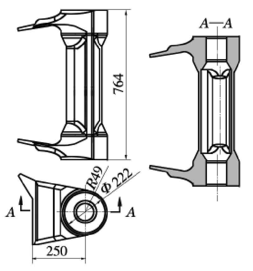
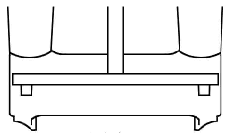
The sand casting of the boss at the root of a boom is made of ZG25, with a total length of 754 mm and a width of 171 mm. It is a thin-walled part as a whole. The thinnest part is 15 mm and the thickest part is 67 mm. The wall thickness difference is large. Casting defects such as shrinkage cavity, porosity and inclusion are not allowed. Through surface fluorescent magnetic particle flaw detection, linear casting defects greater than 2 mm are not allowed (Fig. 1). The product has high technical requirements and it is difficult to adopt integral sand casting process.
According to the casting design manual and combined with the actual production experience, the process scheme of the sand casting is shown in Figure 2: in order to facilitate the placement of the sand core and check the dimensions of all parts after the box is closed, the mold can only be placed horizontally; Carbon dioxide hardened sodium silicate sand and silica sand are used to make core and mold; Since the ears at both ends of the sand casting are the places with the largest wall thickness, the position of the inner gate shall meet the filling and feeding requirements there; According to the principle of sequential solidification, the riser shall be placed at the last solidification place of sand casting to facilitate exhaust and meet the feeding requirements. Therefore, two risers shall be set at the step of shaft lug Φ 150 mm × 300 mm cylindrical riser. The wall thickness difference of sand casting is large, and the sand casting material ZG25 has large sand casting stress, so it is considered to set chill at the place with large wall thickness. In order to prevent the formation of gap cracks at the thin wall in the middle of the shaft hole of sand casting due to the chilling effect of cold iron, this process adopts an external long strip cold iron made of Q235, which is placed horizontally at the bottom of sand casting with a size of 32 mm × 40 mm × 750 mm (Figure 3a).
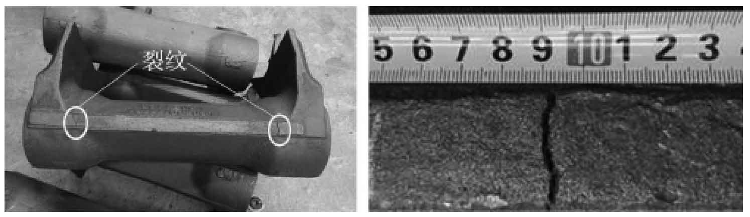
According to the above process optimization, after actual production, it is found that hot cracks appear at the steps of shaft holes of sand castings (Fig. 4). The analysis shows that although the external cold iron is not in direct contact with the thin wall of the shaft hole of sand casting, the spacing between them is small. The cold iron has a certain chilling effect on the thin wall area, resulting in the increase of heat transfer difference and uneven shrinkage between the thick wall and the thin wall, thus increasing the risk of hot crack. Therefore, in scheme 2, the external cold iron should be considered to avoid the thin-wall part, and two cold irons should be placed at the thickest part of the sand casting wall, with a size of 32 mm × 30 mm × 120 mm (Figure 3B). When placing, set an appropriate slope to prevent the gap crack of cold iron.
According to the structural analysis of sand castings, the transition fillet radius between the ear and the shaft is large, which can disperse the stress there. Therefore, scheme 3 is proposed: no chill is set to reduce other casting defects such as pores caused by chill effect of chill (Fig. 3C).
See Table 1 for the comparison of three iron cooling schemes.
| Scheme | Cold iron position | Cold iron size / mm |
| Option 1 | Bottom of casting | Bottom of casting |
| Option 2 | Thick wall at the bottom of casting | 32×30×120 |
| Option 3 | No cold iron | — |