
(1) Design and selection of top riser (Fig. 1)
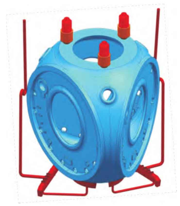
After the mold filling, the molten iron on the top of the casting carries out liquid feeding on the middle and lower parts, so that shrinkage porosity is easy to occur at the cross hot joint on the top. Especially when the bottom injection molding filling time is long, the upper and lower temperature gradients are large, the upper and lower temperature gradients are high, and the liquid shrinkage at the bottom is much larger than that at the top, resulting in the loss of the liquid iron feeding source at the top of the casting. It is necessary to set a top riser, and the modulus of the top riser should be slightly larger than the feeding area at the top. However, the top riser will also bring new cross hot joints. The setting of the riser diameter is unreasonable, and the root of the riser neck is prone to shrinkage and looseness. The riser neck modulus can be appropriately reduced by raising the riser, and the cross hot joints formed between the riser neck and the casting can be cut off during the solidification of the casting.
(2) Design of side riser and blank holder riser
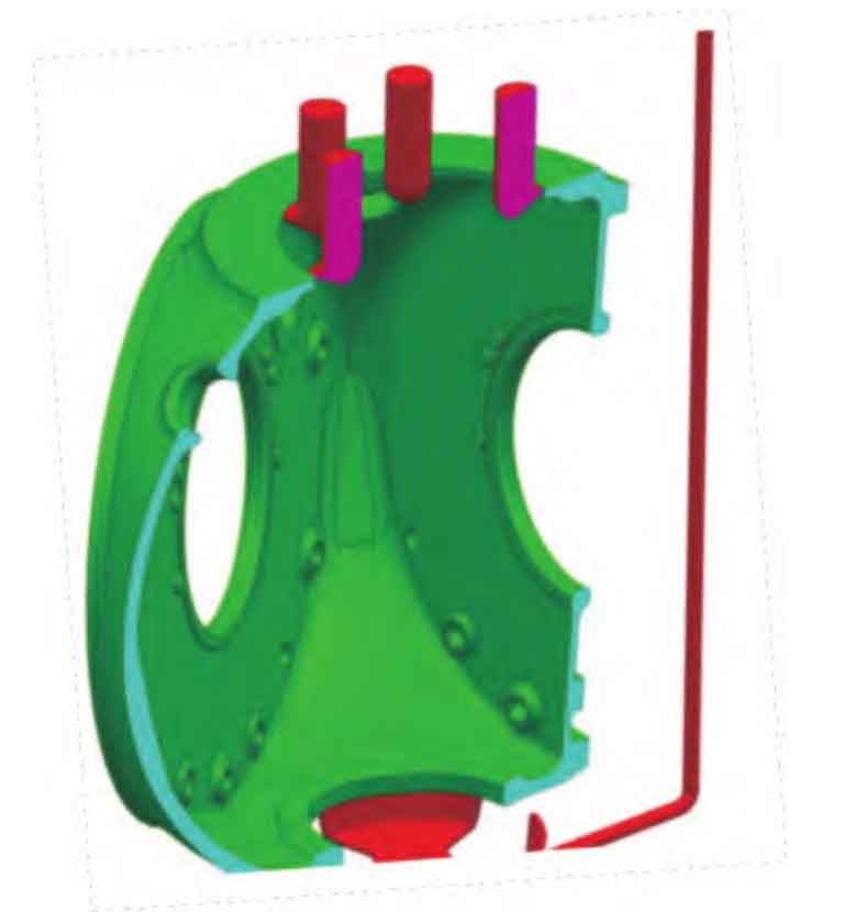
The blank holder riser and side riser will not form new cross hot joints with the casting, and can play a certain role of liquid feeding in the early stage after the completion of mold filling. At the same time, it is easy to knock and remove the casting during cleaning (Fig. 2). However, if the small module riser neck of the blank holder riser or side riser is solidified and closed in advance, the molten iron on the top of the casting is still feeding the middle and lower part, resulting in no liquid feeding source on the top itself, which is easy to form shrinkage porosity and shrinkage cavity defects on the top.