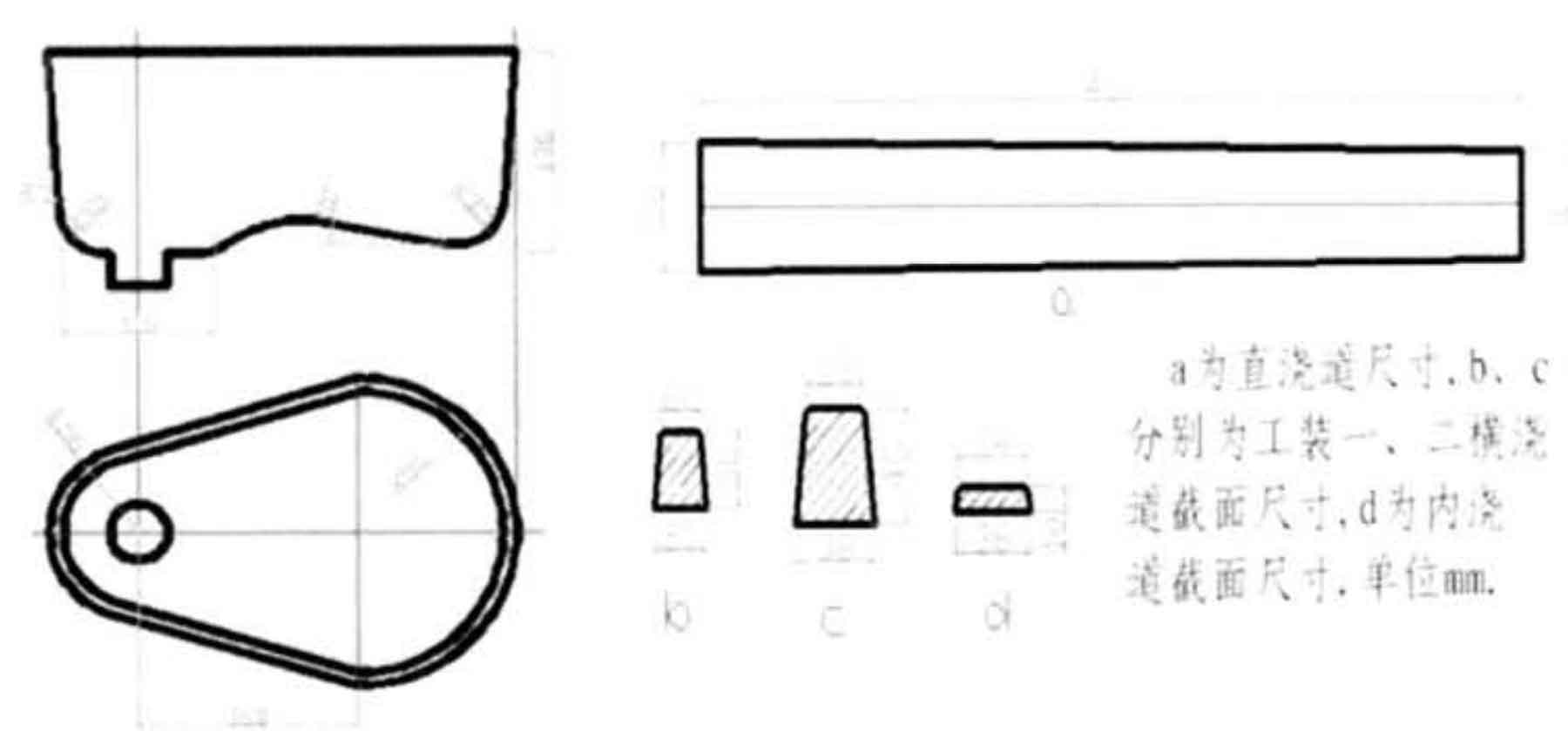
In sand casting, the gating system is a reserved channel in the sand mold, which is used to guide the high-temperature metal melt into the casting cavity and continuously complete the filling of the cavity. The main requirements for the gating system are:
(1) Rapid pouring: reduce the temperature loss during mold filling time, reduce the burning loss of elements and reduce
Less oxidation.
(2) Get clean molten iron: reduce the generation of scum in the pouring process and try to put the scum in the first place
Sieve away during secondary filling.
(3) Economical design: maximize the economic benefits of castings.
The reference dimensions of each component of the gating system are determined by the table lookup method according to the pouring weight and casting modulus and the specific calculation method of individual data according to the formula. Pouring weight:
Casting weight + riser weight = 95 × 2+8.40=198.40kg
Check the attached table in the casting manual and select the basin gate cup. The specific dimensions are shown in Figure 1. Design two sets of gating systems;
(1) Take the direct sprue as the center, set the transverse sprue in two directions, and set two internal sprues on each side of the transverse sprue
The riser is arranged at the end of the inner sprue.
(2) The transverse sprue is set in one direction, the two risers are connected with the inner sprue, and the other two risers are only connected with the casting mold
The cavity is connected.
In the two sets of gating systems, the dimensions of sprue, runner and ingate are taken respectively: the upper section diameter of sprue is d = 42mm, the sectional area of sprue is as = 13.60cm2, the sectional area of runner and am = 13.60cm2, and the sectional area of ingate and Ag = 14.40cm2. The specific dimensions are shown in Figure 2.
As the actual situation of liquid metal pouring into the sprue cup from the crucible changes greatly when the enterprise is pouring on site, the real situation of liquid metal pouring into the sprue cup from the crucible cannot be described in real time and accurately in CAE simulation, so the process of liquid metal entering the sprue is simplified in CAE simulation. After the main dimensions of each part of the pouring and riser are determined, the tooling layout is preliminarily drawn up according to the casting principle and production experience; Ceramic filter screen is set on the runner to reduce the slag entering the casting cavity, and the cross-sectional size of the runner is appropriately increased on the basis of considering the closure effect of the filter screen. Tooling 1: conical extension is adopted at the end of the runner, tooling 2: slag collecting tank is set at the end of the runner, which is conducive to the accumulation of molten slag again. The detailed layout of gating system and Riser: including the length and overlapping mode of transverse sprue and inner sprue, the position where liquid metal is introduced into the casting cavity, the setting position of filter screen and the relative position between gating riser and casting cavity are shown in detail by the following solid tooling and mold design.

