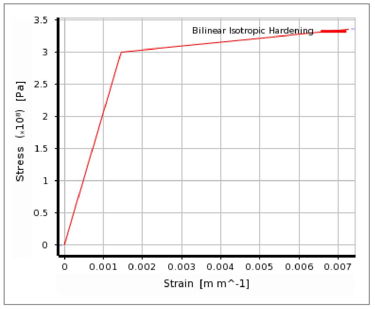
Due to the large stiffness of the main pipe of the cast steel joint, one end of the main pipe is treated as approximate rigid connection, and the load is applied to the other nozzles. This simplification can approximately reflect the working state of the joint. In the calculation, the material characteristics of cast steel adopt bilinear model, and its stress-strain relationship is as follows:
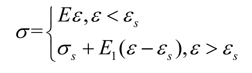
In the formula, e is the elastic modulus of cast steel, which is 2.06 × 10⁵Mpa, 300pa for yield strength and 500MPa for ultimate tensile strength. After entering the plastic stage, multilinear isotropy is adopted according to article 9.1.3 of code for design of steel structures
| Yield strength | Tensile strength | Modulus of elasticity | Shear modulus | Poisson’s ratio | Density |
| 300MPa | 500MPa | 206Gpa | 79Gpa | 0.3 | 7850kg/m3 |
According to the dynamic hardening constitutive relationship, the tangent modulus E1 is taken as 6100mpa.
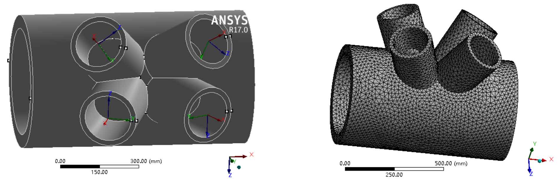
The material properties and working conditions of cast steel joints are shown in table . The ideal elastic-plastic model is used to simulate the constitutive model of cast steel, and the von Mises yield criterion is used to check it. One end of the main pipe is approximately restrained by the fixed end, and the load is applied to the other nozzles. The finite element software is ANSYS, and the element is solid187.
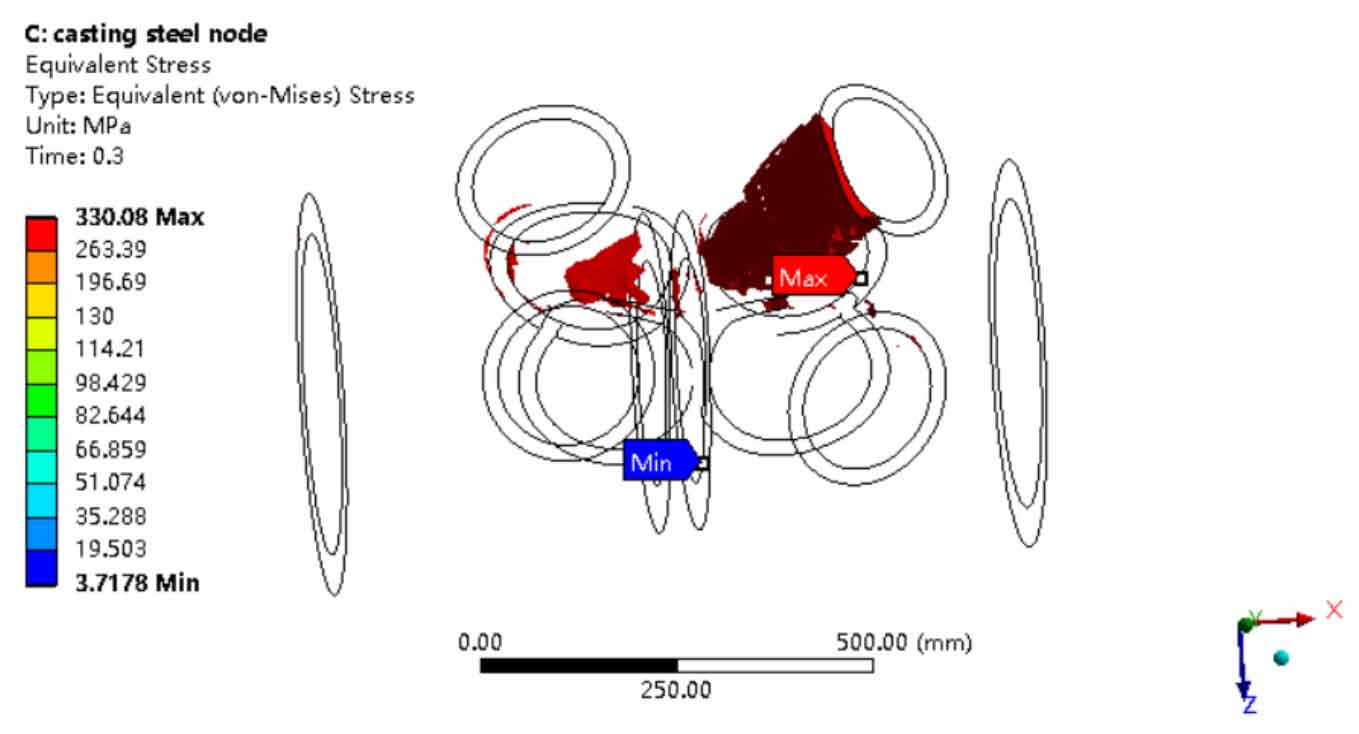
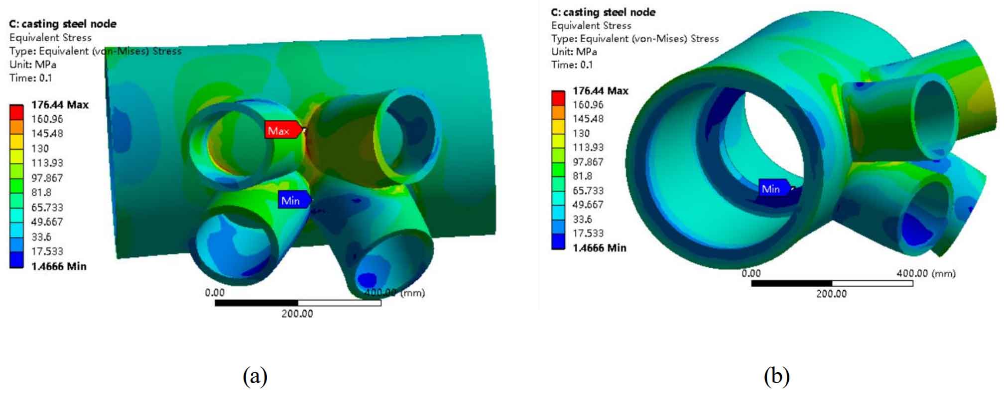
Figure 1 shows the von Mises stress nephogram of cast steel joints under this working condition.
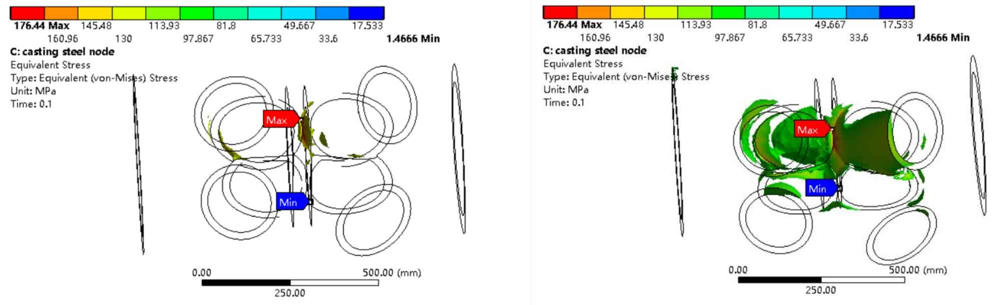
According to the analysis of the finite element calculation results of the above maximum internal force conditions, under the given external load, the cast steel joint is in a linear elastic state as a whole, and the maximum von Mises stress is 176.44mpa. After filtering out the part greater than 120.00mpa (Fig. 2), it is found that the high stress area is only concentrated in the local area where the intersection of the branch pipe and the main pipe is very small, where the stress concentration is easy to occur, but they are less than the design strength.

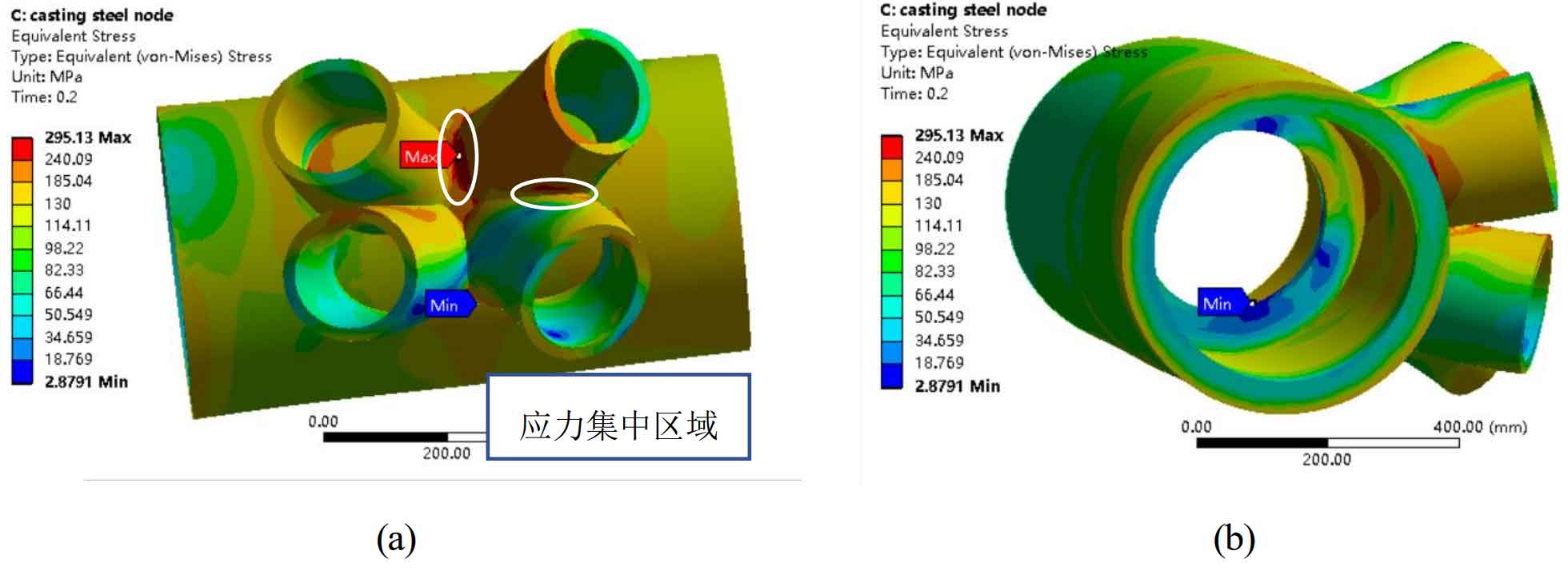
Under the action of twice the load, the maximum stress of cast steel joint has almost reached 300mpa. As shown in Figure 6, the maximum stress of the cast steel joint of the structure under the action of three times the load has reached 330mpa, but it is found that the part exceeding 300mpa is only on one side of branch pipe 2.
Under the design load, the whole joint is in the elastic stage, and the stress of the joint steel casting is far less than the yield strength of the steel casting material. It is still in the linear elastic state and has a great safety margin. However, the stress distribution is not uniform. The stress at the branch pipe is large, while the stress at the main pipe is small. Therefore, the safety assessment of the branch pipe should be focused on, especially near the intersection line between the branch pipe and the main pipe, as well as the rib plate and main pipe connection in the middle of the main pipe. These areas are not only high stress areas, but also areas with concentrated casting defects, which should be paid special attention to in design and production. Because there is no fillet transition, there will be a small part of stress concentration near the intersection line, and the place where the stress concentration is often the place with short fatigue life. If there are casting defects in these areas, the structure will undoubtedly bear greater risks.

Combined with the results of nondestructive testing and casting simulation, the crack is established at the root of the branch pipe of the cast steel joint to evaluate the influence of casting defects on the mechanical properties of the cast steel joint.