1. Microstructure and non-metallic inclusions
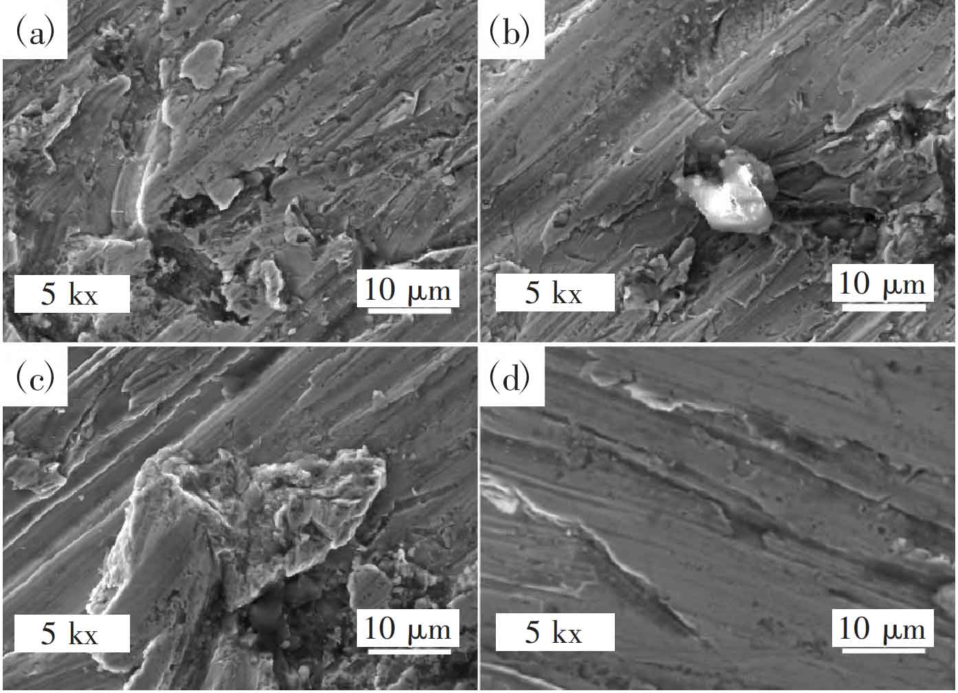
The typical microstructure of two types of experimental cast steel is shown in Figure 1 (where (a) (b) represents No.1 steel, and (c) (d) represents No.2 steel).
It can be seen from the pictures that the microstructure of the two test cast steels after heat treatment is lath tempered sorbite, and there is more tempered sorbite with Flat noodles martensite orientation. Ferrite is in the form of lath, and carbide is dispersed between ferrite Flat noodles or in grains. At the boundary of Flat noodles ferrite, there are two main types of carbides distributed dispersedly, namely spherical M23C6 and short rod M7C3, and the precipitation amount of M23C6 is more than M7C3. After measuring the size of carbides using Image J, it was found that the size of spherical carbides in No.1 cast steel is 20-45 nm, and the size of short rod-shaped carbides is 50-200 nm; In contrast, the size of carbides in No. 2 cast steel is smaller, with spherical sizes ranging from 10 to 45 nm and rod-shaped carbides ranging from 30 to 190 nm.
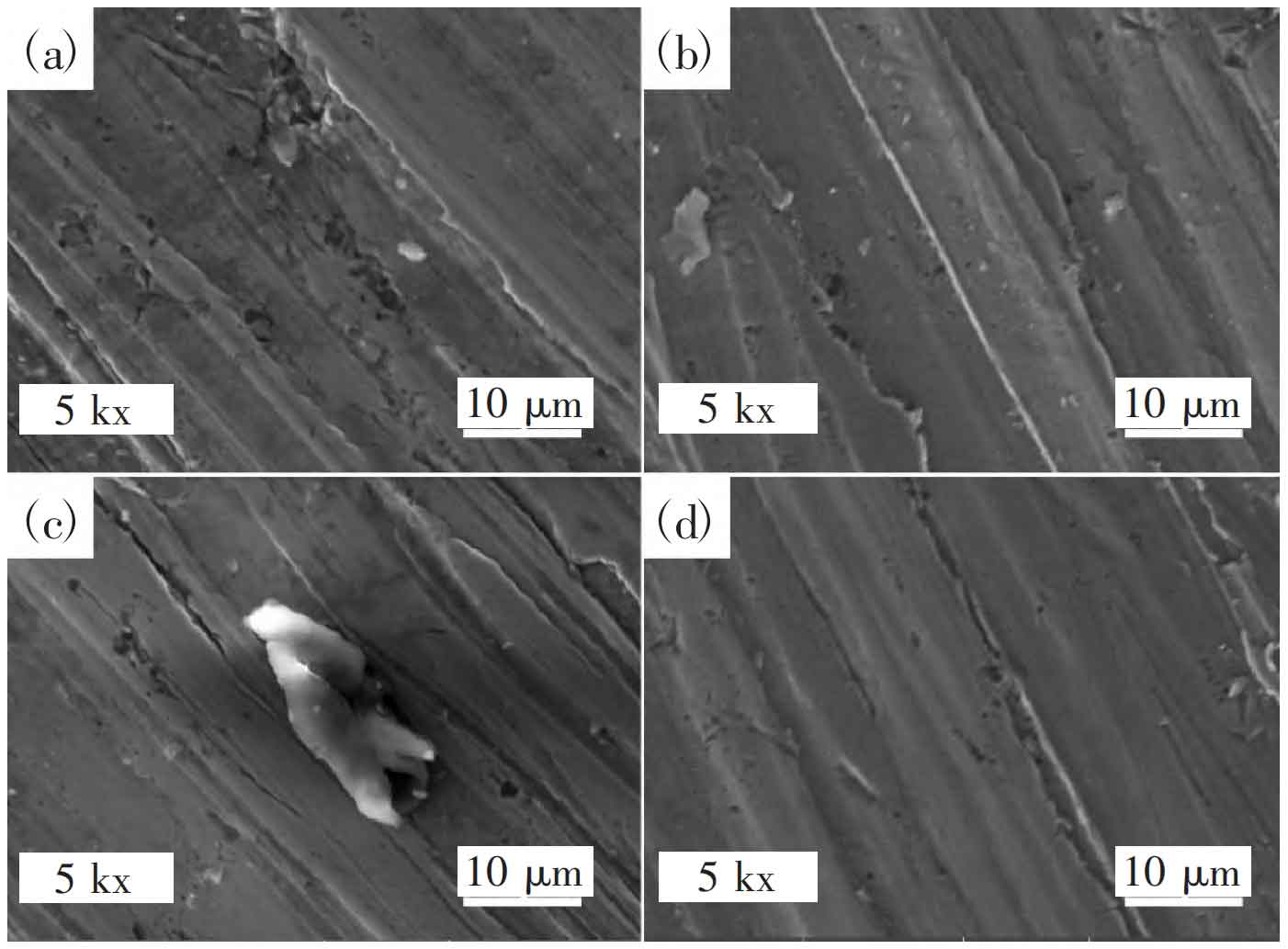
During the casting process of steel, it is inevitable to form some non-metallic inclusions, especially in the production of thick walled steel castings, where defects are often caused by this factor. Large inclusions can have a serious impact on the mechanical properties of steel. The morphology of several typical inclusions in the experimental steel is shown in Figure 2 (where (a) (b) is taken from sample 1, (c) (d) is taken from sample 2): spherical inclusions (a), short rod inclusions (b), long strip inclusions (c), and triangular inclusions (d). After statistical analysis of the number of inclusions with different morphologies in two types of cast steel, it was found that in both types of cast steel, the number of spherical inclusions was the highest, followed by short rod and long strip inclusions, and triangular inclusions were the least.
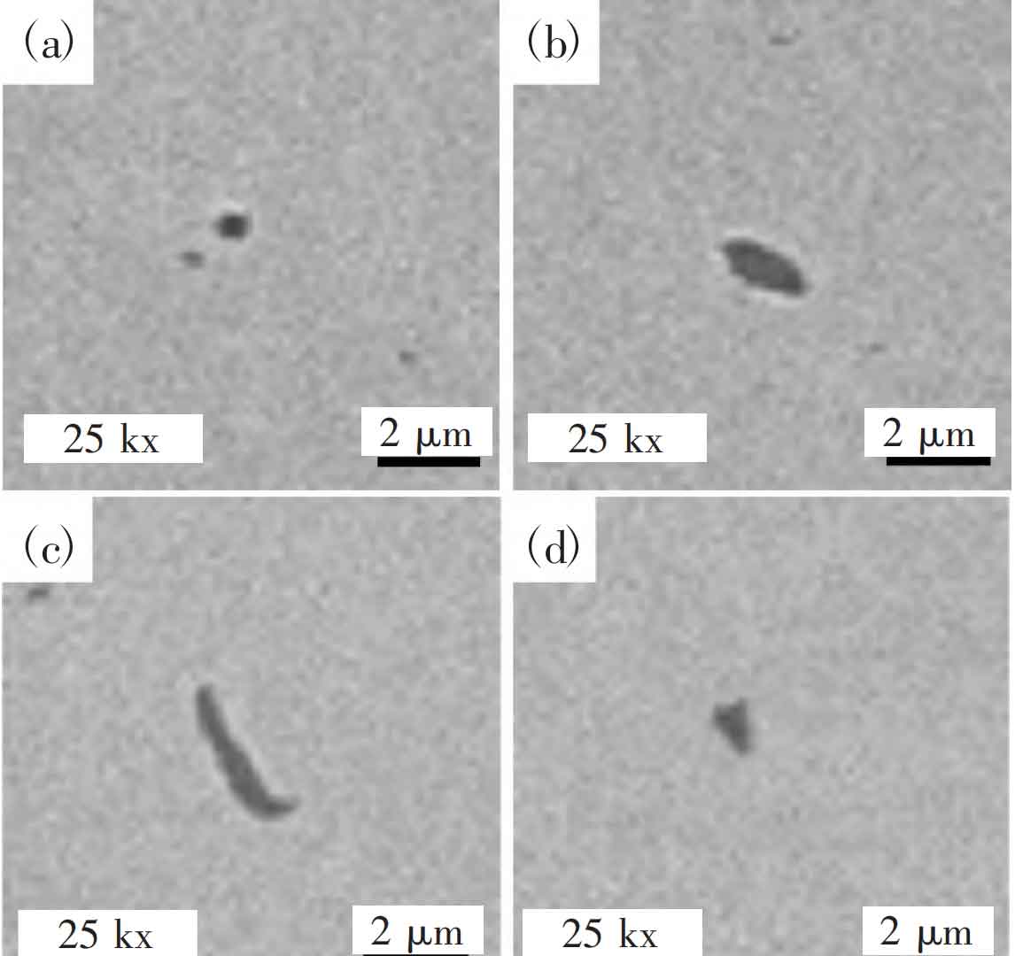
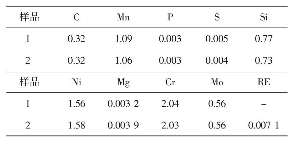
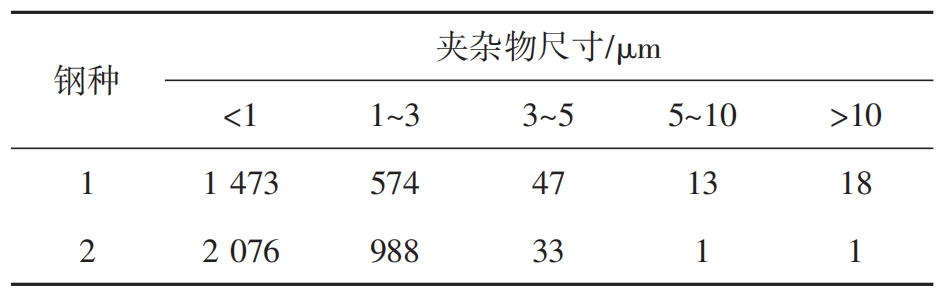
Table 2 summarizes the size and quantity of non-metallic inclusions in two types of experimental cast steel. In the No.1 test cast steel, the size of inclusions is less than 1 μ The quantity of m is the highest, accounting for 69.33%; Next are 1-3 μ m. The proportion is 27.03%; 5~10 μ M and>10 μ There are relatively few inclusions in m; The average size of inclusions is 1.78 μ m. Where size ≤ 5 μ The proportion of m is 98.55%. The highest number of non-metallic inclusions in No. 2 cast steel is still<1 μ m. Accounting for 66.99%; Secondly, the size ranges from 1 to 3 μ M accounts for 31.88%; Size ranges from 5 to 10 μ M and 10 μ The proportion of m and above is the least; The average inclusion size of the second test cast steel is 1.47 μ m. Inclusion size ≤ 5 μ The proportion of m is 99.94%.
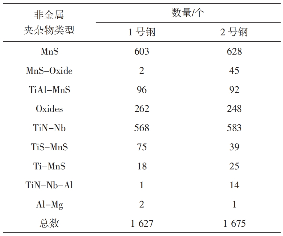
The size, morphology, and composition of inclusions have a significant impact on the performance of the sample. When the size of inclusions exceeds 5 μ When m is present, these non-metallic inclusions can easily become the source of microcracks, thereby reducing the strength and toughness of cast steel and affecting its wear resistance, especially the presence of sulfides and oxides, which can easily lead to unavoidable defects in the cast steel. Table 3 provides statistics on the types and quantities of non-metallic inclusions in two types of steel billets, mainly including oxide inclusions, oxide composite inclusions, sulfide inclusions, sulfide composite inclusions, and nitride composite inclusions. During the cooling process of cast steel, low melting point FeS inclusions can lead to thermal embrittlement, which is usually improved by adding Mn to form MnS. Spherical MnS poses little harm to mechanical properties, but elongated or eutectic MnS can damage the steel matrix and reduce wear resistance; Oxide inclusions mainly include SiO2, Al2O3, and Ti oxides. Al2O3 inclusions are hard and brittle, which can damage the metal matrix, leading to stress concentration and crack formation. In addition, oxide inclusions can also cause surface defects in cast steel; The common nitrides in cast steel include TiN and AlN, which can increase the brittleness of cast steel and lead to brittle transgranular fracture. The supersaturated N element will react with Fe, precipitate Fe2N and Fe4N, and reduce toughness. Usually, Ti, V, and Al elements are added to fix N and eliminate aging tendency.
2. Mechanical properties of cast steel
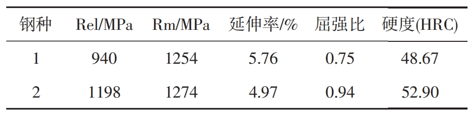
Table 4 compares the mechanical performance data of two types of cast steel. Figure 3 shows the tensile fracture morphology of the two test steels at room temperature, where (a) (b) represents No.1 cast steel and (c) (d) represents No.2 steel. After adding RE element to cast steel, the tensile strength, yield strength, and hardness all increased to varying degrees. Compared with No. 1 cast steel, they increased by 1.59%, 27.45%, and 8.69%, respectively. However, at the same time, the plasticity and toughness of cast steel showed a significant decrease, and the elongation decreased by 0.79%.
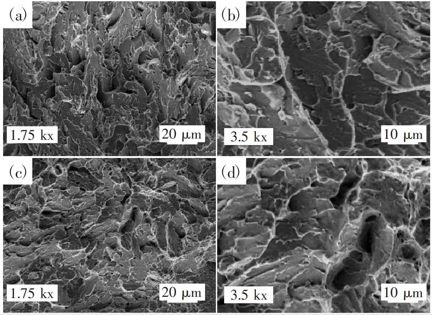
From Figure 3, it can be seen that the tensile fracture surfaces of the two experimental cast steels exhibit similar cleavage fracture characteristics, which means that during the tensile process, the material cracks along certain crystal planes in a specific direction. These cleavage surfaces have relatively smooth edges and certain cleavage steps. There are also numerous white irregular striped tearing edges on the fracture surface of the sample, which may be caused by local stress concentration in the material during the tensile process. In addition, some large-sized and uneven dimples can also be observed on the surface of the fracture. The characteristics of cleavage surface, ductile dimples, and tearing edges collectively reflect that the fracture mechanism of the two experimental cast steels belongs to a mixed ductile brittle fracture.
3. Wear resistance of cast steel
Table 5 provides a detailed record of the numerical changes of the two test steels before and after wear under the same experimental conditions. When the external load is 100 N and subjected to 40 minutes of wear, the wear weight loss of No. 1 steel is 2.579 3 g, while the wear weight loss of No. 2 steel is slightly lower at 2.503 2 g. At different time periods, the wear amount of No. 2 steel is smaller than that of No. 1 steel, and in a short period of time, the difference in wear amount between the two types of steel shows an expanding trend. This fully demonstrates that under the same experimental conditions, the cast steel with the addition of RE element has better wear resistance. In order to more accurately represent the degree of improvement of RE element on the wear resistance of cast steel, the following formula can be used to evaluate: (wear amount of No.1 steel – wear amount of No.2 steel)/wear amount of No.1 steel. The results showed that the wear resistance of cast steel increased by 2.95% after adding RE element. This means that under the same wear conditions, the cast steel with added RE element can withstand longer wear time or greater wear force, thereby extending the service life of the cast steel.
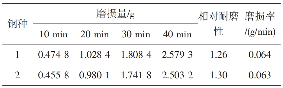
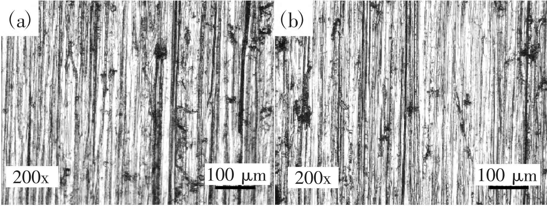
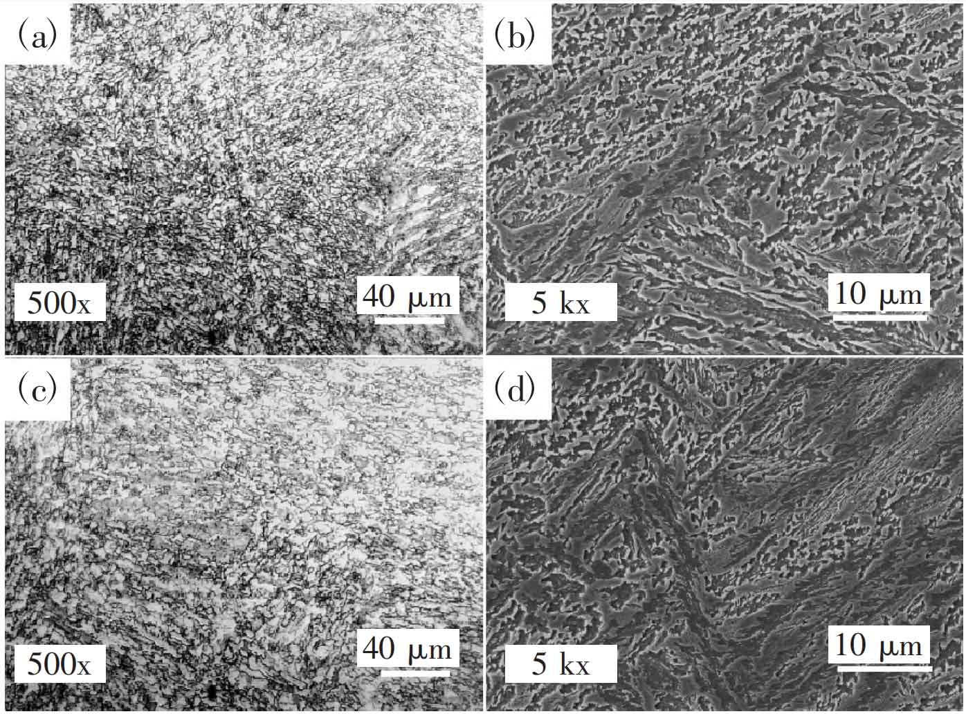
Figure 4 shows the surface morphology under a metallographic microscope, where (a) represents No.1 cast steel and (b) represents No.2 cast steel. From the figure, it can be seen that there are plow grooves with consistent directions on the surface of both types of cast steel at low magnification. However, after adding RE element to the cast steel, both the density and depth of the plow grooves are reduced. The ground surface morphology of two types of cast steel under scanning electron microscopy is shown in Figures 5 and 6. In Figure 5, the main wear mechanisms are microcracks, furrows, embedded abrasive particles, and plastic accumulation. Figure 5 (d) shows that the wear morphology of the sample is mainly dominated by sliding wear, and there are numerous deep and significant cutting marks distributed on the wear surface, showing a uniform distribution characteristic; Figure 5 (a) clearly reveals that under the influence of long-term contact stress, the surface layer of the specimen undergoes significant plastic deformation. This phenomenon further leads to the generation of cracks. As the crack propagates, local materials will gradually detach from the surface in layers; Figure 5 (b) shows the situation where abrasive particles are embedded on the surface of the specimen, and the presence of plowing grooves can also be observed. This is because when the friction surface starts sliding, the test cast steel surface is subjected to the plowing effect of raised hard points, resulting in plastic shear and the production of abrasive particles on the surface material. The vertical pressure embeds the quartz sand into the worn surface, and when sliding, these abrasive particles are pushed forward, resulting in the formation of plow grooves on the worn surface; The presence of furrow waves can also be observed in Figure 5 (c). The wear mechanism is mainly micro cutting, accompanied by slight fatigue damage. The wear surface morphology of No. 2 cast steel is similar to that of No. 1 cast steel (as shown in Figure 6), but the number of pits formed by sand particle detachment is relatively small, and the depth of the plow groove is also relatively shallow.