
Abstract: In order to improve the efficiency and fuel consumption indexes of excavators, an orthogonal test optimization technology of the bucket tooth for the excavator based on joint simulation was proposed. By conducting the material property test, a discrete element model of real soil was built, while a dynamic model of the excavator was built as well. Based on the joint simulation of multi-body dynamics and discrete element, the accurate simulation of the excavation process for the excavator was achieved. Then a bucket tooth optimization method based on orthogonal test was proposed, and the bucket tooth were optimized by using the orthogonal test. At the same time, for the first time in the field of domestic engineering machinery, the metal 3D printing technology was used to produce the optimized bucket tooth and then the optimized bucket tooth was installed for actual testing. The result showed that the optimized bucket tooth achieved an improvement in the efficiency and fuel consumption indexes of excavators.
1. Introduction
Engineering construction machinery is widely used in municipal construction, water conservancy projects, national defense, and military industries, as well as mining operations [1]. Hydraulic excavators, known as the crown jewel of engineering machinery, have operational efficiency and fuel consumption as two critical performance indicators. These indicators are not only the goals of design but also key indicators reflecting the core competitiveness of enterprises [2]. Most of the energy consumed during hydraulic excavator operations is used to overcome the digging resistance. Therefore, reducing the digging resistance is essential to improving the excavator’s efficiency and fuel consumption indexes [3].
The bucket teeth of an excavator are located at the tip of the bucket and are the components that directly contact the material. During operation, the bucket teeth cut through the material, and the cutting force directly affects the overall digging resistance. The outer dimensions of the bucket teeth are closely related to their soil-breaking performance [4]. To optimize the shape of the bucket teeth, it is necessary to analyze the influence of each geometric parameter of the bucket teeth on the digging resistance to facilitate structural optimization. Common analysis methods at home and abroad mainly include the empirical formula method and the discrete element method [5]. The empirical formula method reproduces the actual digging trajectory of the bucket teeth by building a dynamic model, but the calculation is relatively rough, and the results cannot reflect the optimization effect of the bucket teeth [6]. Regarding the bulk material characteristics of the excavation objects, the discrete element method has been applied to the calculation of digging resistance by numerous domestic and foreign scholars over the years. When using the discrete element method for calculation, the shape of the bucket teeth does not need to be simplified, and the impact of shape changes will be reflected in the results. However, the actual digging trajectory is complex, and relying solely on the simple motion trajectory provided by the discrete element software often deviates from reality. Based on the above research, the author adopted a combined simulation of dynamics and the discrete element method to simulate the actual digging process of the excavator and combined the orthogonal test method to optimize the bucket teeth of a certain model of Sany. The bucket teeth optimization technology based on dynamics-discrete element joint simulation was proposed, and metal 3D printing technology was used to manufacture the optimized bucket teeth, which were then installed for actual testing of operational efficiency and fuel consumption.
2. Establishment of Discrete Element Simulation Model
2.1 Discrete Element Technique
In the 1970s, Professor Cundall P. A. of the United States first proposed the discrete element method for the analysis of discrete materials [7]. This technique separates the research object into several independent particles with mass and shape. The contact relationship between particles conforms to Newton’s laws of motion. Through iterative calculations, mechanical equilibrium between particles is achieved within a small calculation step, and the microscopic displacement of each particle is calculated in real-time. This approach enables the macroscopic motion state of the material to be derived from the microscopic perspective.
2.2 Establishment and Calibration of the Discrete Element Model
The discrete element software used by the author is EDEM, the world’s first professional CAE software specifically designed to solve complex discrete material systems. By setting the particle shape and related properties, a discrete element model conforming to the flow characteristics of real soil was established. To this end, the author conducted material property tests on the soil at the test site and calibrated the discrete element model accordingly. The author selected the Hertz-Mindlin contact model with JKR V2 suitable for soil in EDEM. The calibration parameters included the coefficient of restitution and other parameters [9]. The material property tests mainly included drop tests, inclined plane tests, angle of repose tests, etc. The correspondence between the material property tests and model parameters, and the calibrated soil discrete element model parameters are listed in Tables 1 and 2.
| Table 1. Basic Parameters of Soil |
|---|
| Material |
| Poisson’s Ratio |
| Shear Modulus (Pa) |
| Density (kg·m^-3) |
| Table 2. Contact Parameters of Soil |
|---|
| Contact Type |
| Coefficient of Restitution |
| Static Friction Coefficient |
| Rolling Friction Coefficient |
3. Multi-Body Dynamics-Discrete Element Joint Simulation
3.1 Multi-Body Dynamics Model Establishment
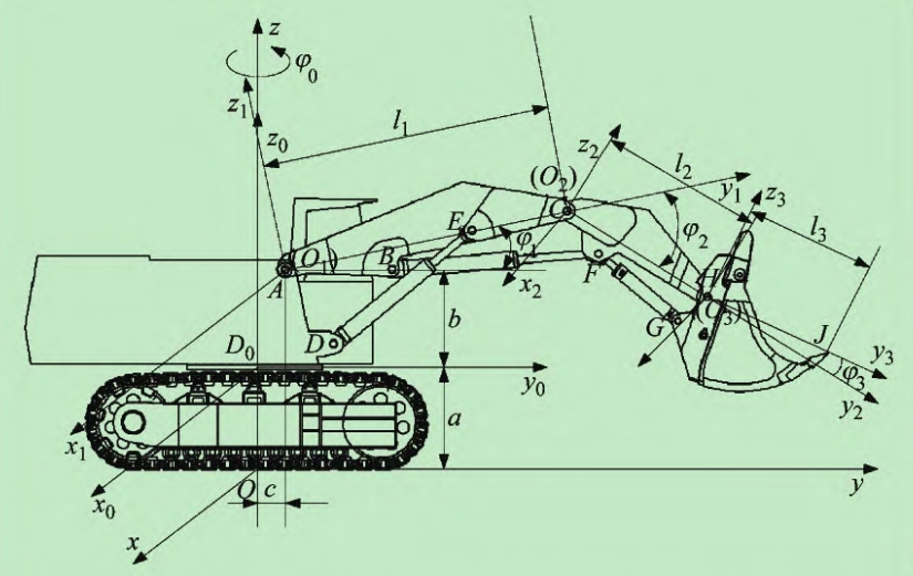
The multi-body dynamics software used by the author is RecurDyn, developed by FunctionBay Corporation of South Korea. This software was used to build a dynamic model of the excavator, which was appropriately simplified. The model is driven by the displacement of the excavator boom, arm, and bucket hydraulic cylinders, ensuring that the excavator perfectly reproduces the actual digging posture.
3.2 Dynamics-Discrete Element Joint Simulation
The actual digging trajectory is complex, and the EDEM software can only achieve simple motions such as translation and rotation. However, with the advancement of software, EDEM and RecurDyn have now opened interfaces with each other, enabling bidirectional interaction of simulation data. This provides a new way to study issues related to bulk materials under complex operating trajectories. The RecurDyn software excels in processing model motions, while the EDEM software excels in solving and analyzing discrete materials. The coupling of the two achieves both accurate reproduction of the excavator’s operating posture and real-time simulation of the digging process, making the final simulation results close to reality. The joint simulation of a certain model of Sany. The joint simulation accurately simulates the digging process of the excavator. By comparing the simulation and measured hydraulic cylinder pressures, the results show that the maximum error of the boom hydraulic cylinder pressure is 17.3%, the maximum error of the arm hydraulic cylinder pressure is 21.7%, and the maximum error of the bucket hydraulic cylinder pressure is 25.0%. The simulation accuracy meets the requirements and also reflects the correctness of the discrete element model calibration.
3.3 Simulation Evaluation Indicators
Relying on EDEM’s powerful data analysis capabilities and considering that the purpose of bucket teeth optimization is to improve the excavator’s operational efficiency and fuel consumption, the author used the mass of material excavated per bucket (hereinafter referred to as the bucket-filling ratio, kg), the energy consumed during the digging process (hereinafter referred to as energy consumption, J), and the energy consumed per unit mass of material excavated (hereinafter referred to as specific energy consumption, J/kg) in the simulation results as simulation evaluation indicators. These indicators indirectly represent the operational efficiency, fuel consumption, and digging economy during actual operations, respectively.
4. Orthogonal Test Method for Bucket Teeth Optimization
4.1 Orthogonal Test Method
Taking the bucket teeth of a certain model of Sany as an example, its key geometric design factors are shown in Table 3. The influence trends of each geometric factor on the final simulation results are not the same, so the experimental design should consider all factors comprehensively. Compared with the full factorial method, the orthogonal test method selects representative factor combinations from the full factorial test based on the principle of orthogonality. These combinations have the characteristics of “uniform dispersion and neat comparability,” which not only allow for the examination of all factors but also meet the requirements of fewer test times and higher efficiency [10]. Therefore, the orthogonal test method was selected to design the simulation test plan for bucket teeth optimization.
Table 3. Geometric Design Factors of Bucket Tooth
| Factor Name | Symbol | Factor Name | Symbol |
|---|---|---|---|
| Upper Angle | R1 | Groove Width | R5 |
| Lower Angle | R2 | Groove Depth | R6 |
| Tip Width | R3 | Groove Chamfer | Alpha |
| Tip Height | R4 | Groove Length | Beta |
| Groove Slope | Theta |
4.2 Experimental Design and Data Analysis
To improve optimization efficiency, important factors were screened from the nine factors of the bucket teeth. The Plackett-Burman design method with N = 12 was used for important factor screening, adopting a 9-level 2-factor test, and a Pareto chart was used to analyze the test results to find the four most significant factors affecting the results. The test design and simulation results are listed in Table 4. The Pareto analysis of the test results. The four most significant factors affecting the bucket-filling ratio, energy consumption, and specific energy consumption are the lower angle R2, tip width R3, tip height R4, and groove slope theta. This provided the basis for the subsequent orthogonal test optimization.
Table 4. Plackett-Burman Test Results
| R1 (°) | R2 (°) | R3 (mm) | R4 (mm) | R5 (mm) | R6 (mm) | Alpha (°) | Beta (mm) | Theta (°) | Energy Consumption (J) | Bucket-Filling Ratio (kg) | Specific Energy Consumption (J/kg) |
|---|---|---|---|---|---|---|---|---|---|---|---|
| 17 | 10 | 10 | 6 | 60 | 6 | 4 | 6 | 5 | 143289 | 1366.3 | 104.8 |
| 17 | 17 | 6 | 10 | 60 | 6 | 6 | 6 | 5 | 145499 | 1310.8 | 110.9 |
| 10 | 17 | 9 | 6 | 72 | 10 | 4 | 5 | -5 | 141775 | 1338.2 | 105.9 |
| 17 | 10 | 10 | 6 | 60 | 6 | 6 | 6 | 5 | 145945 | 1371.9 | 106.3 |
| 17 | 17 | 6 | 10 | 72 | 10 | 4 | 5 | -5 | 148602 | 1322.7 | 112.3 |
| 17 | 17 | 10 | 6 | 60 | 6 | 6 | 6 | 5 | 145658 | 1324.4 | 109.9 |
| 10 | 10 | 10 | 6 | 72 | 10 | 4 | 5 | -5 | 144685 | 1330.6 | 108.7 |
| 10 | 17 | 10 | 6 | 60 | 6 | 6 | 6 | 5 | 1341.6 | 147755 | 107.1 |
| 10 | 17 | 9 | 6 | 72 | 10 | 4 | 5 | -5 | 1354.2 | 149595 | 110.4 |
| 17 | 10 | 9 | 6 | 72 | 6 | 6 | 6 | 5 | 1327.1 | 147755 | 104.9 |
| 10 | 10 | 10 | 6 | 60 | 10 | 4 | 5 | -5 | 1365.6 | 140499 | 108.1 |
| 10 | 17 | 9 | 6 | 60 | 6 | 6 | 6 | 5 | 1334.0 | 143707 | 105.3 |
For the four significant factors, R2, R3, R4, and theta, a 4-factor 3-level orthogonal test was conducted. The test plan was designed according to the L9(34) orthogonal table, and the simulation results were analyzed to explore the influence trends of various factors of the bucket teeth on each evaluation indicator and find the optimization direction. The test plan and simulation results are listed in Table 5.
Table 5. L9(34) Orthogonal Test Results
| R1 (°) | R2 (°) | R3 (mm) | R4 (mm) | R5 (mm) | R6 (mm) | Alpha (°) | Beta (mm) | Theta (°) | Energy Consumption (J) | Bucket-Filling Ratio (kg) | Specific Energy Consumption (J/kg) |
|---|---|---|---|---|---|---|---|---|---|---|---|
| 12 | 7 | 96 | 5 | 6 | 8 | 4 | 5 | -3 | 139960 | 1345.2 | 104.0 |
| 12 | 7 | 10 | 8 | 6 | 8 | 3 | 8 | 0 | 143436 | 1328.9 | 107.9 |
| 12 | 7 | 11 | 10 | 6 | 8 | 4 | 8 | 7 | 144597 | 1366.4 | 105.8 |
| 12 | 12 | 96 | 8 | 6 | 8 | 3 | 8 | 7 | 142188 | 1325.0 | 107.3 |
| 12 | 12 | 10 | 5 | 6 | 8 | 4 | 5 | 0 | 143718 | 1306.2 | 110.0 |
| 12 | 12 | 11 | 10 | 6 | 8 | 3 | 5 | -3 | 140786 | 1362.5 | 103.3 |
| 12 | 14 | 96 | 10 | 6 | 8 | 4 | 8 | 0 | 141783 | 1356.5 | 104.5 |
| 12 | 14 | 10 | 5 | 6 | 8 | 3 | 8 | -3 | 140356 | 1347.0 | 104.8 |
| 12 | 14 | 11 | 8 | 6 | 8 | 4 | 5 | 7 | 141174 | 1342.3 | 104.5 |
The following can be observed:
- R4 has the greatest impact on digging energy consumption and bucket-filling ratio. As R4 decreases, energy consumption decreases, the bucket-filling ratio increases, and specific energy consumption decreases. Therefore, R4 can be appropriately reduced to improve digging economy.
- R3 has the second-greatest impact on digging energy consumption and bucket-filling ratio. As R3 increases, energy consumption first increases and then decreases, the bucket-filling ratio first decreases and then increases, and specific energy consumption first increases and then decreases. During optimization, R3 can be increased.
- As R2 increases, energy consumption decreases, the bucket-filling ratio increases, and specific energy consumption decreases.
- As theta decreases, energy consumption decreases, the bucket-filling ratio also decreases, but specific energy consumption decreases.
4.3 Bucket Tooth Optimization Scheme Results
Drawing on the research detailed in Section 4.2, the bucket teeth were optimized with the primary goal of enhancing digging efficiency, ensuring that fuel consumption remained largely unchanged. The comparison of geometric parameters between the original and optimized bucket teeth is outlined in Table 6. Joint simulations were subsequently performed on both the original and optimized designs. The findings indicate that the optimized bucket teeth achieved a notable 3.3% increase in bucket-filling ratio, accompanied by a marginal 0.75% rise in energy consumption. Importantly, there was a 2.45% improvement in specific energy consumption. These results clearly demonstrate that the optimization objectives were successfully met.
Specifically, the optimized bucket teeth exhibited enhanced performance across the key evaluation metrics, thereby validating the effectiveness of the orthogonal test-based optimization approach combined with joint simulation technology. The increased bucket-filling ratio suggests improved digging efficiency, while the marginal increase in energy consumption, coupled with the notable reduction in specific energy consumption, underscores the optimized design’s ability to enhance operational economy.
In summary, the presented optimization scheme for bucket teeth, grounded in rigorous research and validated through practical testing, offers a promising solution for improving the efficiency and fuel economy of hydraulic excavators. This approach not only advances the state-of-the-art in bucket tooth design but also highlights the potential of advanced manufacturing techniques such as metal 3D printing in the engineering machinery sector.