
Abstract
This paper focuses on the casting process optimization of self – priming pump castings. The pump casting, a crucial part of the canned pump, has complex structures and requires excellent mechanical properties. The initial casting process was designed based on relevant theories and actual production conditions, and casting simulation software was used to predict possible casting defects. Through optimization measures such as adjusting the gating and feeding systems and optimizing production process parameters, the final casting process scheme was determined. The optimized process significantly reduced casting defects and improved the process yield. The research think and methods were verified by production verification tests, proving their feasibility for guiding actual production.
1. Introduction
1.1 Centrifugal Pump Overview
1.1.1 Centrifugal Pump Classification
| Classification Method | Types | Characteristics |
|---|---|---|
| Suction Characteristics | Single – suction Pump Casting | Medium flows in from one direction, simple structure, suitable for small – flow applications such as agricultural irrigation. |
| Double – suction Pump Casting | Medium flows in from both directions, suitable for large – flow and stable operation requirements. | |
| Number of Stages | Single – stage Pump Casting | Only one impeller in the pump cavity, suitable for low – head applications. |
| Multi – stage Pump Casting | Multiple impellers in the pump cavity, can achieve high head, suitable for high – mountain water supply and other working conditions. | |
| Pump Shaft Direction | Horizontal Pump Casting | Shaft is parallel to the horizontal plane, convenient for pipeline connection, but large footprint. |
| Mid – split Pump Casting | Casing is located in the middle of the shaft, combining the characteristics of single – stage and double – suction pumps. | |
| Casing Form | Volute Pump Casting | Forms a volute with a spiral – shaped chamber, simple structure, wide application range, the most common centrifugal pump. |
| Turbine Pump Casting | Casing with a guide vane – equipped pressure chamber, high pump efficiency, but complex structure. | |
| Special Structure | Canned Pump Casting | Pump casing and motor are integrated, achieving completely leak – free operation, widely used in the chemical and nuclear energy industries. |
| Pipeline Pump Casting | Pump casting inlet and outlet have the same diameter as the pipeline, can be installed at any position on the pipeline. | |
| High – temperature Pump Casting | Pump casing has an outer insulation jacket structure, can transport high – temperature media, suitable for special industries such as petroleum and chemical engineering. | |
| Self – priming Pump Casting | Pump casing has a gas – liquid separation chamber and other special structures, can start without manual priming of the medium, suitable for extracting media from low places or frequent pump start – up occasions. |
1.1.2 Self – priming Pump Development and Application
Self – priming pump casting were first successfully developed in Germany in 1917 and have since been continuously improved in various countries. They are widely used in chemical, agricultural, and urban sewage disposal industries due to their unique advantages. Common self – priming pumps include jet – type, water – turbine – ring – type, gas – liquid – external – mixing – type, and gas – liquid – internal – mixing – type, each with different characteristics in pump efficiency, production cost, self – priming time, head, and service life. In engineering applications, gas – liquid – mixing – type self – priming pumps are commonly used, which can be further divided into external – mixing and internal – mixing types.
1.1.3 Key Castings Description
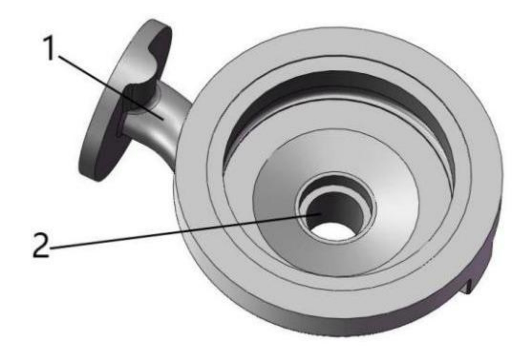
1.1.3.1 Pump Casting
The pump casting is a shell that contains and transports liquid, mainly composed of a suction chamber and a pressure chamber. It has complex structures and high requirements for size, shape, and surface roughness. The pump casting needs to have good mechanical properties to withstand high pressure.
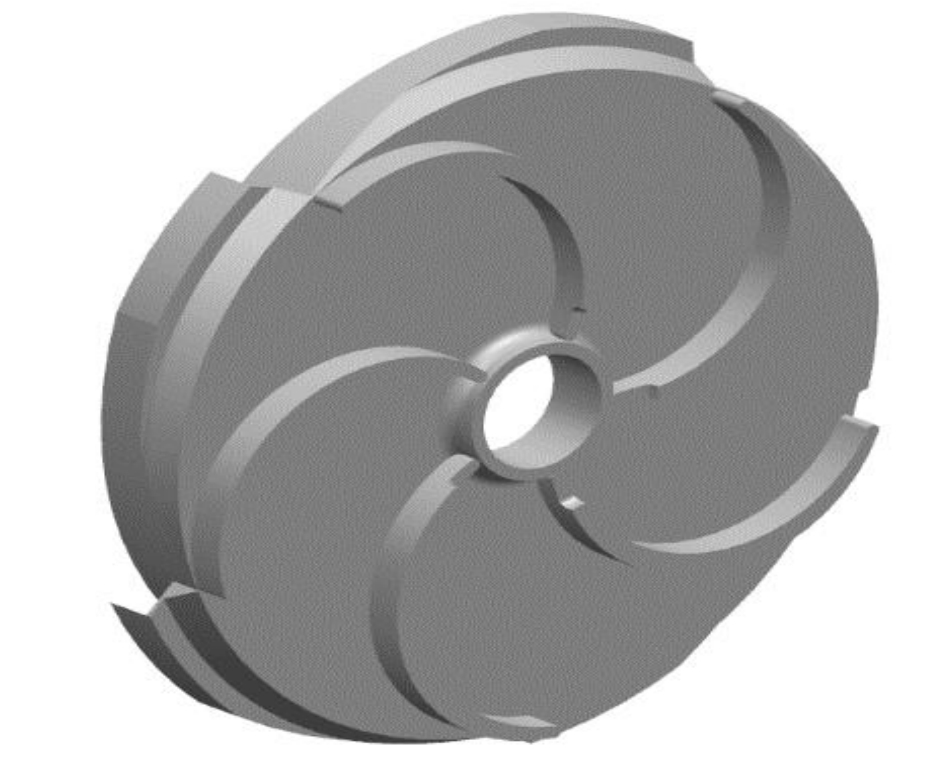
1.1.3.2 Impeller
The impeller is a rotating body with blades that transfers energy to the liquid. The shape and size of the blades are crucial for the pump’s performance, and the casting needs to ensure accurate blade dimensions and good mechanical properties to resist cavitation.
1.1.3.3 Guide Vane
Guide vanes are used in multi – stage pumps to improve the head by converting part of the liquid’s kinetic energy into pressure energy. The accurate shape and size of the guide vanes are essential for the hydraulic performance of the pump casting.
1.2 Key Castings’ Casting Process Scheme
1.2.1 Casting Process Scheme Design
The common casting methods for pump castings include sand casting, metal casting, investment casting, and shell molding casting. Each method has its own characteristics and application scopes. The casting process scheme design generally includes determining the casting method, designing the molding and core – making methods, pouring position and parting surface, other process parameters, pouring and feeding systems, and process equipment.
1.2.2 Casting Process Optimization
Traditional casting process optimization methods have limitations, and more scientific methods are needed. Common optimization methods include mathematical statistics method, Niyama criterion method, TRIZ method, and DOE method. These methods can help reduce casting defects and improve casting quality. Numerical simulation technology is also widely used in casting process optimization to predict defects and optimize the process before casting.
1.2.3 Casting Process Optimization Examples
In recent years, many casting process optimization examples have emerged in the manufacturing industry. For example, some companies have developed new casting processes or optimized existing processes to improve the quality and production efficiency of pump castings. Numerical simulation technology has been widely applied in these optimization processes.
1.3 Development and Application of Casting Numerical Simulation Technology
1.3.1 Foreign Development
Casting numerical simulation technology started in the 1940s and has since developed rapidly. Scholars have conducted research on various aspects such as temperature field, stress change, and microstructure simulation. Commercial casting simulation software has also been developed, with powerful functions and wide application ranges.
1.3.2 Domestic Development
Domestic research on casting numerical simulation started later than that in developed countries. After years of development, domestic research has made significant progress, and some domestic casting simulation software has also been developed with high calculation accuracy.
1.3.3 Application Status and Development Trend
1.3.3.1 Application Status
Casting simulation software can now simulate the entire casting process, including mold filling, solidification, and defect formation. It can also analyze the temperature field, velocity field, pressure field, and microstructure of the casting, providing a basis for process optimization.
1.3.3.2 Development Trend
The future development trend of casting numerical simulation technology is to achieve more comprehensive and accurate simulation of the casting process, from raw material smelting to casting heat treatment. The goal is to improve the quality and efficiency of casting production and reduce costs.
1.4 Significance and Research Contents of the Project
1.4.1 Project Significance
The self – priming pump casting studied in this project is a key component of a new self – priming canned pump. With the increasing demand for leak – free pumps in the chemical industry, optimizing the casting process of the pump casting is of great significance for ensuring the quality and performance of the pump casting and promoting the application of the pump casting in the market.
1.4.2 Research Contents
This project aims to optimize the casting process of the ZG07Cr19Ni10 stainless steel self – priming pump casting. The research includes designing the casting process, analyzing and comparing the simulation and actual defects, optimizing the casting process scheme, and conducting production verification tests to ensure that the castings meet the quality requirements.
2. Casting Simulation Theory and Software Introduction
2.1 Theory Basis
2.1.1 Filling Stage
The filling process of molten metal in the mold is a complex physical process that can be described by fluid mechanics equations, including the continuity equation, N.S equation, and energy equation. Turbulence models, such as the standard k – ε turbulence model and the RNG k – ε model, are often used to simulate the turbulent flow of molten metal. The oxidation slag generated during the filling process can also be calculated using relevant equations.
2.1.2 Solidification Stage
The solidification process of the casting involves heat transfer, and the heat transfer equation, such as the Fourier heat conduction equation, is used to describe the temperature change during solidification. The convection heat transfer and radiation heat transfer between the metal and the mold are also considered.
2.1.3 Simulation Methods for Shrinkage Cavity and Porosity
Common methods for simulating shrinkage cavity and porosity defects include the isothermal solidification method, temperature gradient method, Niyama criterion method, and residual melt modulus method. These methods can predict the location and size of defects and provide a basis for process optimization.
2.2 Casting Simulation Software Introduction and Usage Process
This project uses Flow – 3D cast software for casting process simulation. The software can accurately simulate the fluid flow and heat transfer process, and its operation is simple and convenient. The usage process of the software mainly includes importing the 3D model, setting material parameters, heat transfer coefficients, initial conditions, and output parameters, and then performing numerical calculations and analyzing the results.
3. Pump Casting Processability Analysis and Process Scheme Design
3.1 Casting Processability Analysis
3.1.1 Structure and Usage Requirements Analysis
The pump casting has a complex structure with a large overall size and significant differences in wall thickness. The casting needs to meet high requirements for corrosion resistance, strength, and dimensional accuracy. The casting process needs to be carefully designed to avoid defects such as insufficient filling and shrinkage cavities.
3.1.2 Material Analysis
The pump casting is made of austenitic stainless steel ZG07Cr19Ni10, which has good corrosion resistance. However, this material is prone to casting defects such as slag inclusions, cold shuts, shrinkage cavities, and porosity. Appropriate casting process parameters and measures need to be selected to avoid these defects.
3.2 Process Scheme Design
3.2.1 Molding and Core – making Methods
Considering the production conditions and the complexity of the pump casting shape, this project adopts the manual molding and core – making method. The sand used for molding and core – making is water glass carbon dioxide hardened sand and ester hardened alkaline phenolic resin sand, which can meet the requirements of casting production and avoid some casting defects.
3.2.2 Pouring Position and Parting Surface
The pouring position and parting surface are designed based on the principles of sequential solidification and ease of molding and demolding. The pump casting is placed horizontally with the inlet flange at the bottom and the large flange at the top. Two parting surfaces are set to facilitate the production of sand cores and ensure the accuracy of the casting dimensions.
3.2.3 Other Process Parameters
Other process parameters, such as casting shrinkage rate, dimensional tolerance, draft angle, parting allowance, and exhaust system, are also determined according to the characteristics of the casting and production conditions to ensure the quality and dimensional accuracy of the casting.
3.2.4 Pouring System
The initial pouring system design adopts a stepped gating system with two inner gates. The pouring time is calculated based on the weight of the casting and related coefficients, and the minimum cross – sectional area of the inner gate is determined using the choke section design method. The dimensions of each part of the pouring system are designed to ensure the smooth flow of molten metal and avoid casting defects.
3.2.5 Feeding System
The initial feeding system design uses heat – insulating risers and chills to ensure sequential solidification of the casting. The risers are placed at thick – walled and large – sized parts, and the chills are used to improve the feeding effect and reduce the size and number of risers.
3.2.6 Casting Auxiliary Materials
The selection of casting auxiliary materials, such as furnace charge, silica sand, and coating, is also crucial. The furnace charge is mainly composed of recycled steel and silicon iron, and the silica sand and coating need to meet certain quality requirements to ensure the quality of the casting surface.
3.2.7 Smelting Process
The pump body casting is smelted using a medium – frequency induction furnace, and the metal liquid is refined and adjusted to the appropriate temperature and composition before pouring. The pouring temperature and the temperature of the sand mold are also important process parameters that affect the quality of the casting.
4. Pump Body Casting Process Optimization
4.1 Initial Process Scheme Simulation Analysis
4.1.1 Filling Process
The simulation results of the initial process scheme show that the molten metal has severe turbulence at the beginning of filling, resulting in the formation of oxidation slag. The temperature field and pressure field are also affected, and the upper inner gate has a negative impact on the filling process.
4.1.2 Solidification Process
During the solidification process, the initial scheme shows that there are isolated liquid phase regions in some parts of the casting, which may lead to shrinkage cavity and porosity defects. The temperature field also indicates that there are thermal nodes in some areas, which affect the sequential solidification of the casting.
4.1.3 Shrinkage Cavity and Porosity Defects
The simulation results using the residual melt modulus criterion show that shrinkage cavity and porosity defects are mainly concentrated in thick – walled parts and the transition areas between thick and thin walls. These defects may affect the performance and service life of the pump casting.
4.2 Casting Actual Defects
The actual casting defects observed after production include cold shots, wrinkled skin, cracking, and hole – like defects. These defects are mainly located in the flange, boss, and partition areas of the pump casting.
4.3 Defect Analysis and Prevention Measures
4.3.1 Defect Analysis
The defects are analyzed using scanning electron microscopy and other methods. The results show that the cracking defects are actually continuous shrinkage cavities and porosity caused by poor heat dissipation in the hot spots of the casting. The hole – like defects are also due to slag inclusions that prevent the flow of molten metal and lead to insufficient feeding, resulting in shrinkage cavities and porosity.
4.3.2 Prevention Measures
Based on the defect analysis, the following prevention measures are proposed: optimizing the pouring system to ensure smooth filling and reduce the formation of oxidation slag; optimizing the feeding system to promote sequential solidification and ensure sufficient liquid feeding at the hot spots; increasing the compactness of the sand mold to prevent mold wall expansion and casting shrinkage defects; fully baking the mold cavity to keep it dry and avoid gas pores and cold shots; and increasing the pouring temperature and speed to enhance the fluidity of the molten metal and reduce the content of oxidation slag.
4.4 Pouring System Optimization and Simulation Analysis
4.4.1 Optimization Scheme 1
4.4.1.1 Pouring System Optimization Design
In the first optimization scheme, the upper inner gate is removed, and the pouring system is changed from open to closed. The cross – sectional area of the runner is reduced, and the inner gate is introduced tangentially into the flange. A straight runner well is also added to improve the flow state of the molten metal.
4.4.1.2 Simulation Results
The simulation results of the optimized pouring system show that the temperature field remains basically unchanged, the maximum pressure increases slightly but is still within a reasonable range, and the speed field shows that although the initial speed of the molten metal in the inner gate is significantly reduced, local turbulence still occurs at the flange, which may lead to slag inclusions. Therefore, further optimization is needed.
4.4.2 Optimization Scheme 2
4.4.2.1 Pouring System Optimization Design
In the second optimization scheme, a horizontal runner is added between the inner and straight runners to trap gas and slag. The pouring system is changed from closed to semi – closed, and the cross – sectional area of the inner gate is slightly increased.
4.4.2.2 Simulation Results
The simulation results show that the optimized pouring system has a reasonable temperature field and pressure field, and the speed field is stable with a small speed difference. The molten metal can fill the mold cavity smoothly without turbulence, indicating that this optimization scheme is reasonable and effective.
4.5 Feeding System Optimization and Simulation Analysis
4.5.1 Optimization Scheme 1
4.5.1.1 Feeding System Optimization Design
The first optimization scheme reduces the size and number of risers and adds chills at appropriate positions to control the solidification sequence and prevent shrinkage defects.
4.5.1.2 Simulation Results
The simulation results of the solidification process show that although the optimization scheme reduces the size of the shrinkage cavity and porosity defects, there are still some isolated liquid phase regions in the casting, and the horizontal and vertical feeding distances of the risers are insufficient, requiring further optimization.
4.5.2 Optimization Scheme 2
4.5.2.1 Feeding System Optimization Design
The second optimization scheme increases the size and number of risers in some areas and optimizes the position and size of the chills to improve the feeding effect and ensure the sequential solidification of the casting.
4.5.2.2 Simulation Results
The simulation results show that the optimized feeding system can effectively reduce the shrinkage cavity and porosity defects, and the casting can achieve sequential solidification. The process yield is also increased, indicating that this optimization scheme is reasonable and effective.
5. Pump Casting Production Process Parameter Scheme Research
5.1 Orthogonal Test Scheme Design
An orthogonal test is designed to optimize the production process parameters of the pump casting. The factors selected for the test are pouring temperature, sand mold preheating temperature, and pouring time, with three levels for each factor. The test uses an L9(3^4) orthogonal table, and the test indicators include the velocity and oxidation slag concentration in the inner gate during the filling process, and the solidification time and hole – like defect volume of the casting during the solidification process.
5.2 Orthogonal Test Results Analysis
5.2.1 Filling Process
5.2.1.1 Velocity Field Analysis
The velocity field analysis of different schemes shows that the velocity difference in the inner gate affects the filling stability. Schemes L3 and L6 have relatively stable filling processes, while scheme L9 has a large velocity fluctuation and poor filling stability.
5.2.1.2 Oxidation Slag Concentration Analysis
The analysis of the oxidation slag concentration in the inner gate shows that the concentration is affected by the filling time. Shorter filling times can reduce the contact time between the molten metal and air, resulting in less oxidation slag. Schemes L1 and L6 have relatively low oxidation slag concentrations.
5.2.1.3 Pressure Field Analysis
The pressure field analysis shows that the pressure in the inner gate is affected by the filling time. Shorter filling times can increase the pressure, but excessive pressure may damage the mold cavity. Schemes L6 and L8 have reasonable pressure fields that can maintain the stability of the mold cavity.
5.2.1.4 Significance Analysis
The significance analysis of the filling process indicators shows that the pouring time has a significant impact on the velocity, oxidation slag concentration, and pressure in the inner gate, while the pouring temperature and sand mold preheating temperature have relatively small impacts.
5.2.2 Solidification Process
5.2.2.1 Temperature Field Analysis
The temperature field analysis of different schemes shows that the temperature gradient and cooling rate during solidification affect the quality of the casting. Schemes L5 and L8 have better temperature gradients and can ensure the continuous feeding of the casting.
5.2.2.2 Solid – Liquid Phase Distribution Analysis
The analysis of the solid – liquid phase distribution shows that the optimization of the process parameters can improve the sequential solidification of the casting and reduce the formation of isolated liquid phase regions. Schemes L6 and L7 have better solid – liquid phase distributions and fewer shrinkage cavity and porosity defects.
5.2.2.3 Significance Analysis
The significance analysis of the solidification process indicators shows that the pouring temperature and sand mold preheating temperature have significant impacts on the solidification time and hole – like defect volume of the casting, and their influence trends are similar. The pouring time also has an impact on the hole – like defect volume, and a reasonable pouring speed can reduce the formation of defects.
5.3 Optimal Production Process Parameter Scheme
Based on the above analysis, the optimal production process parameter scheme is determined as follows: pouring temperature of 1590°C, sand mold preheating temperature of 300°C, and pouring time of 15s. This scheme can ensure the smooth filling of the molten metal, reduce the formation of casting defects, and improve the quality of the casting.
6. Verification Test
6.1 Production Verification
A casting production verification test is carried out according to the optimized casting process scheme and production process parameters. The castings are subjected to solution treatment after casting.
6.2 Casting Test Results
6.2.1 Chemical Composition Testing
The chemical composition of the test bars is tested, and the results show that the main chemical components meet the acceptance requirements.
6.2.2 Metallographic Structure Testing
The metallographic structure and grain size of the test bars are tested, and the results show that the α phase content and grain size meet the requirements of the pump casting material.
6.2.3 Mechanical Property Testing
The mechanical properties of the test bars are tested, and the results show that the yield strength, tensile strength, elongation, impact absorption energy, and Brinell hardness all meet the mechanical property standards.
6.2.4 Radiographic Testing
The flange and other thick – walled parts of the pump casting is tested by radiographic testing, and the results show that no 超标 defects are found, and the rating is Class I.
6.2.5 Pressure – bearing Capacity Testing
The pressure – bearing capacity of the pump casting is tested by water pressure test and gas leak test. The results show that the pump casting passes the 2.2MPa N₂ gas leak test and 3MPa water pressure test, and the results are qualified.
The verification test results show that the castings produced by the optimized casting process meet the quality requirements, which proves that the research ideas and methods in this paper are feasible for guiding actual production.
7. Conclusion
In this study, the casting process of the self – priming pump casting was optimized. The initial casting process was designed and simulated, revealing issues such as turbulent metal flow during filling and an unreasonable temperature field during solidification, leading to casting defects. Through optimization of the pouring and feeding systems, a semi – closed pouring system was designed, achieving stable metal flow with a velocity difference less than 0.5m/s, a reasonable temperature difference of 110°C, and a maximum pressure of 0.15MPa. The optimized feeding system enabled sequential solidification with reduced shrinkage cavity and porosity defects. Orthogonal tests were conducted to optimize production process parameters, determining the optimal combination as a pouring temperature of 1590°C, sand mold preheating temperature of 300°C, and pouring time of 15s. Verification tests on the castings produced under these optimized conditions showed that they met all quality requirements, validating the effectiveness of the proposed process optimization methods for guiding actual production and providing valuable references for similar casting processes.