
Abstract: This paper focuses on the sand casting process design and optimization for large hydraulic turbine volute casings, aiming to reduce production costs, shorten the production cycle, and improve production efficiency. The study determines the appropriate casting process parameters, gating systems, and optimizes the casting process using Any-Casting simulation software. The results demonstrate the feasibility of using the sand casting method for hydraulic turbine volute casings.
1. Introduction
Hydraulic turbines consist of intake, water-guiding, working, discharging, and non-flow components. The volute casing, as a structural component, provides stiffness and supports the turbine, often serving as the bearing point for the turbine and accommodating the water-guiding mechanism and its transmission devices. This paper discusses the sand casting process design, solidification simulation, and process optimization for single-piece, small-batch production of large hydraulic turbine volute casings.
2. Structural Analysis and Modeling of the Turbine Volute
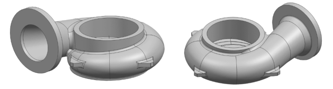
The volute casing, working in conjunction with guide vanes and rotors, ensures that water from the pressure pipe is introduced into the water-guiding mechanism uniformly and axially symmetrically with minimal flow loss. The casing’s shape resembles a spiral with a gradually changing radius. The overall dimensions are 1622.5mm × 814mm × 1510.3mm, with a maximum wall thickness of 110mm and a minimum thickness at the sharp-angled structure where the cylindrical channel meets the impeller. Four lugs are symmetrically arranged on the casing, and a flange disk is located at the inlet. A diameter of 120mm hole runs through the middle cylindrical ring base.
Table 1: Chemical Composition of QT500-7 (in wt%)
| Element | C | Si | Mn | P | S | Mg |
|---|---|---|---|---|---|---|
| Composition | 3.55-3.85 | 2.34-2.86 | <0.60 | <0.08 | <0.025 | 0.02-0.04 |
3. Casting Process Design
3.1 Casting Material and Production Type
The volute casing is made of QT500-7 material, and production is single-piece, small-batch.
3.2 Casting Process Scheme
Given the casing’s large size and uneven wall thickness, a sand casting process using furan resin self-hardening sand for manual molding is employed. The mold and core surfaces are coated with alcohol-based paint to form a refractory protective layer. Cracks, holes, corners, and uneven areas are repaired with adhesive and sprayed with silver graphite powder for easy mold release.
3.3 Determination of the Parting Surface
The casting structure necessitates a two-box stepped parting surface. The axis of the flange disk inlet does not align with the volute pipe and its four lugs, necessitating a stepped parting surface for easy molding, mold withdrawal, core positioning, and shakeout.
3.4 Gating System Design
An open middle-inlet gating system is selected for its stable metal filling, minimal sand core impact, low metal oxidation, and strong slag-trapping ability. The dimensions of the gating system are calculated using the cross-sectional area ratio method, with F内:F横:F直 = 1.0:2.0:1.5. The gating system includes six ingates, with the runner surrounding the casing’s largest cross-section. Additional 60mm flow channels at both ends of the runner prevent metal backflow, ensuring smooth filling and slag trapping.
Table 2: Gating System Dimensions
| Component | Cross-Sectional Area (cm²) | Dimensions |
|---|---|---|
| Sprue Resistance (F阻) | 73.86 | Height: 650mm, D1=60mm, D2=55mm |
| Runner (F横) | 147.8 | Trapezoidal, l1=94mm, l2=112mm, Height=144mm |
| Ingate (F直) | 110.8 | Flat ingate, L1=62mm, L2=70mm, Height=68mm |
3.5 Riser Design
Considering the graphite expansion of nodular iron and the multi-ingate system promoting synchronous cooling and solidification, a riser-less design with eight 30mm vents is adopted.
4. Core Process Design
4.1 Core Design
The spiral shape of the volute casing necessitates a spiral core made of furan resin self-hardening sand. Divided into two parts (1# and 2#), the removable core includes core bones and is assembled with wax threads and vent holes for easy exhaust.
4.2 Core Support Design
To stabilize the tall core, low-carbon steel core supports with threads and grooves to prevent leakage are used. Calculated using the strength method, four single-light column circular core supports (DGY100) are evenly distributed on the large base.
5. Solidification Simulation and Optimization
5.1 Solidification Simulation
Using Any-Casting software, the casting process is simulated with a pouring temperature of 1390°C and a pouring time of 34s. The metal enters the mold through six ingates, filling the volute pipe first and the central cylindrical wall and flange top last.
5.2 Defect Analysis and Cold Iron Addition
Simulation reveals slag inclusion defects at the thinnest and interior walls. To mitigate defects, graphite electrode cold iron with a thickness of 80mm, width of 80mm, and length of 200mm is added.
6. Conclusion
- The sand casting method using resin-bonded sand cores is suitable for producing large turbine volute casings.
- A closed gating system with no risers yields a feasible casting process.
- Simulation using Any-Casting validates the design, predicts defect locations, and optimizes the process by adding cold iron.