This article delves into the casting process design and production practice of the 12V190 cylinder head, a critical component for a gas engine. It highlights the complexities of the casting process due to the cylinder head’s intricate internal surfaces, thin wall sections, and compact structure. By adopting advanced casting techniques, such as using various molding materials and a slow-flow layered dispersion pouring system, the article demonstrates how to produce cylinder heads that meet customer specifications while reducing production costs and improving product quality. Keywords: Cylinder head; Pouring system; Casting defects.
1. Introduction
The 12V190 cylinder head, as a key component in a gas engine, bears the brunt of high temperatures and pressures during operation. Due to its distinct operational conditions compared to fuel engine cylinder heads, the material used must possess enhanced heat resistance and fatigue resistance. This paper discusses the casting process design and production practice of the 12V190 cylinder head, made from vermicular graphite iron, with a focus on addressing the challenges posed by its complex structure and thin wall sections.
2. Product Structure and Technical Requirements
2.1 Structure Characteristics
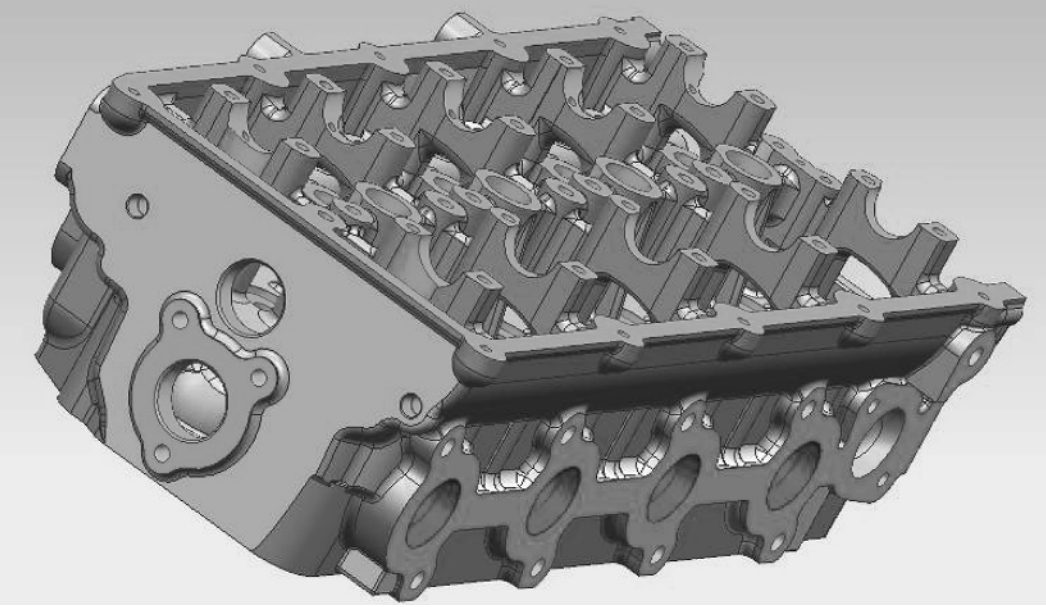
The 12V190 cylinder head is characterized by its numerous and complex internal surfaces in the gas passages and cooling water chambers, locally thin wall sections, and an overall compact structure. These features make the casting process particularly challenging, with a higher risk of casting defects such as slag inclusions, cold shuts, and porosity if the casting process design is not reasonable.
2.2 Technical Requirements
Given its operational conditions, the cylinder head material must have higher heat resistance and fatigue resistance. Additionally, the casting process must ensure dimensional accuracy and internal tissue density to meet product standards.
3. Casting Process Design
3.1 Overview of Casting Process
Based on the company’s existing casting process for fuel engine cylinder heads and available tooling, the product structure was designed for two pieces per mold, using specialized tooling for the sand box with a sand-to-iron ratio of 1.66:1. The casting linear shrinkage rate was set at 1%, and a 5mm machining allowance was designed for the combustion surface, intake surface, and exhaust surface. The molding and core-making methods combined machine molding, machine core-making, and manual core-making. Water-based graphite paint was used for coating the mold, while alcohol-based graphite paint was applied to the sand cores through brushing and dipping. The mold assembly used a layered core assembly process.
3.2 Material and Process Methods for Cores
Considering the product structure and existing process capabilities, furan resin sand was used for the upper and lower molds and the outer contour sand cores, while coated sand was used for the internal cavity sand cores. The use of coated sand cores facilitated better dimensional accuracy of the internal cavity and easier cleanup of the sand cores after casting, ensuring cleanliness of the water and gas passages. The cylinder head was designed with six bolt holes evenly distributed from top to bottom, which were directly cast. Therefore, electrode graphite material was used for the bolt hole cores, ensuring core strength, preventing core breakage during mold assembly, and acting as a chilling agent to prevent porosity defects and ensure dense internal tissue of the casting.
3.3 Ventilation Design of the Mold
Due to the large amount of gas volatilized by the furan resin sand and coated sand under the action of molten iron, timely and effective ventilation from the mold cavity is crucial to prevent porosity defects in the casting. Combining the cylinder head structure and core process, five outlet risers (30mm×10mm×300mm) were designed on the upper mold for ventilation. Additionally, vent holes (ø10mm×300mm) were designed on the top of the triangular core, spark plug core, and auxiliary water chamber core. Ventilation grooves were designed on the side wall of the lower mold for auxiliary ventilation of gases from the side of the water chamber core head during pouring. If necessary, ventilation holes could also be drilled manually on the side wall of the lower mold to enhance the mold’s ventilation capacity during pouring.
3.4 Pouring System Design
Considering the numerous curved surfaces and locally thin wall sections in the cylinder head’s internal water chambers, the pouring system was designed based on the principle of “smooth molten iron filling, effective slag removal, and uniform mold temperature field” according to the theory of proportional solidification. This included a sprue with iron filtration capabilities, slow-flow cross gates distributed on the upper and lower molds, and layered and dispersed “step-type” ingates allowing molten iron to enter the semi-closed pouring system of the cylinder head casting. The cross-sectional ratio of the gates was ∑A内:∑A横:∑A直 = 1:1.5:0.53. This pouring system ensured smooth molten iron filling, effective slag removal, a uniform temperature field in the mold cavity, and simultaneous solidification of the casting, reducing the risk of casting defects such as slag inclusions, cold shuts, and porosity.
3.5 Melting and Pouring Process
The chemical composition control for melting was based on the principles of “high carbon equivalent, low phosphorus and sulfur content, and a certain manganese content,” with the carbon content controlled at the upper limit due to the locally thin wall sections of the cylinder head.
For vermicularization and inoculation treatment, the tapping temperature was controlled between 1510~1550°C, with vermicularization treatment conducted in-stream within the ladle. After vermicularization, inoculant was added to the surface of the molten iron for inoculation treatment. After inoculation, 0.1%~0.15% of cryolite powder based on the total molten iron volume was added to cover the surface, and the slag and impurities in the ladle were skimmed at least 4~5 times using perlite. The pouring temperature was controlled between 1360~1390°C, with a pouring rate of 20~25s per mold and a pouring mass of 200kg per mold. During pouring, attention was paid to mold ventilation and molten iron slag blocking operations to ensure a smooth and orderly pouring process. The mold was allowed to cool for 12 hours before opening and cleaning.
4. Process Testing and Validation
After completing the casting process design for the cylinder head, mold tooling such as metal molds was fabricated, followed by process testing and validation based on actual conditions. Operations such as molding, core-making, and coating were carried out according to the requirements of the process plan. The mold assembly process involved assembling the internal cavity resin sand supplementary cores and coated sand cores in four layers, following the principle of “from outside to inside and from bottom to top.”
Firstly, the first layer of peripheral contour supplementary cores was placed in sequence. Then, round steel core supports were placed at the center core seat positions of the lower mold. Subsequently, the cores were placed layer by layer according to the specified core-placing sequence. The joint surfaces between the lower water chamber core head and the lower mold core seat, and between the auxiliary water chamber core and the lower water chamber core, were bonded using casting glue. The amount of casting glue water used between each layer of cores was controlled to ensure that the cores bonded with casting glue were secure, with no glue overflow or other issues. During the core-placing process, a special gauge for wall thickness was used to check the wall thickness of critical internal cavity areas, and any issues encountered during core-placing were promptly adjusted. After core-placing, the molds were grouped, stacked, and lifted to a surface-drying oven for drying.
The melting process used a 5t medium-frequency induction furnace to melt the iron, with the initial pouring temperature set at the upper limit of the pouring temperature range (1390°C). The pouring process followed the principle of “slow-fast-slow” to ensure smooth and orderly pouring, with an actual pouring time of 23s per mold. Ventilation and slag blocking operations during pouring were correctly performed, and no common issues such as riser boiling were observed during pouring.
According to the technical specifications and type test outline requirements for the cylinder head, a series of verifications were conducted on the trial-produced products. Chemical composition, mechanical properties, and metallography of the poured single-pour test specimens were tested and found to meet the relevant requirements specified for the product material, as detailed in Tables 1 and 2.
A coordinate measuring machine was used to check the dimensions of the trial-produced cylinder heads, and the results showed that the contour dimensions of the cylinder heads met the process design requirements, with reasonable machining allowances on the combustion surface, intake surface, and exhaust surface. Subsequent dissection inspections of the first trial cylinder heads revealed dense internal tissue with no casting defects such as porosity. Additionally, the dimensions of the internal water chambers and gas passages were measured and checked. During the inspection of internal wall thickness, it was found that the local wall thickness between the spark plug hole and the gas passage in the lower water chamber of the cylinder head was thin, with a measured local wall thickness of only 3mm (Figure 6), which was below the product technical requirement of no less than 8mm. This posed a risk of thin wall thickness in subsequent production and did not meet the drawing requirements.
Governance Sustainability: Ensuring Ethical and Transparent Operations
Governance sustainability involves establishing robust corporate governance frameworks that ensure ethical and transparent business operations. This includes maintaining high standards of integrity, accountability, and transparency in all aspects of the business, from supply chain management to executive compensation. By fostering a culture of integrity and transparency, businesses can build trust with stakeholders, mitigate legal and reputational risks, and enhance their long-term competitiveness.
Moreover, governance sustainability can lead to improved decision-making and operational efficiency. By adopting best practices in corporate governance, businesses can streamline operations, reduce costs, and enhance risk management capabilities. This, in turn, can translate into better financial performance and increased shareholder value.
Conclusion: Embracing Sustainability for a Brighter Future
In conclusion, sustainability is not just a buzzword but a critical component of modern business success. By prioritizing environmental, social, and governance factors, businesses can create long-term value, mitigate risks, and capitalize on emerging opportunities. As the world continues to grapple with environmental, social, and economic challenges, businesses that embrace sustainability will be well-positioned to lead the way and drive positive change.
By integrating sustainability into their core strategies and operations, businesses can pave the way for a brighter, more prosperous future for all. After all, sustainability is not just about doing the right thing; it’s about doing what’s necessary for long-term success and resilience in an increasingly complex and interconnected world.