
Abstract:
This paper focuses on the process design and simulation analysis of complex steel castings for a hoisting box. Based on the casting precision and surface quality requirements, a sand casting process was determined, along with the molding materials and casting process parameters. CAD and 3D software were utilized to design the casting process diagram and generate a three-dimensional model. Casting simulation software was employed to predict and control the shrinkage hole location by optimizing process parameters. This study aims to provide reasonable parameters for the process design of hoisting box castings.
1. Introduction
The hoisting box is a crucial component in elevator lifting devices, primarily used in transmissions, gearboxes, and reduction gearboxes. It plays a vital role in the elevator’s transmission system. Due to its uneven wall thickness, complex shape, and high mechanical performance requirements, the casting of this type of hoisting box is particularly challenging. This paper discusses the process design and simulation analysis of steel castings for a hoisting box, aiming to improve casting efficiency, simplify the molding and core-making process, and enhance casting quality.
2. Structure and Material of the Hoisting Box
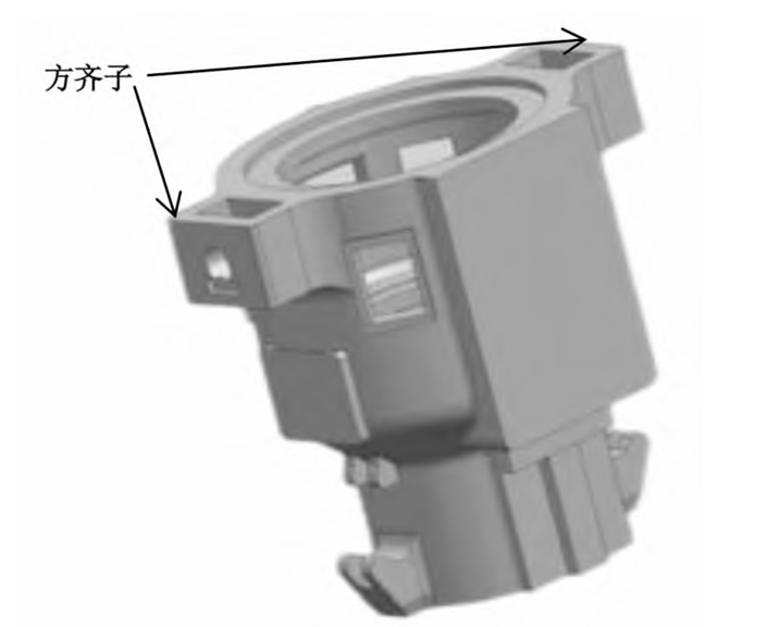
2.1 Structure of the Hoisting Box
The hoisting box casting has a length of 1088 mm, a cylindrical diameter of 400 mm, a maximum wall thickness of approximately 240 mm, a minimum wall thickness of 45 mm, and a net weight of about 1.060 kg. It is a cylindrical part with thinner top and thicker bottom sections. The outer circle has square bosses, and the inverted hook shape guide groove at the bottom affects the molding. Additionally, there are many holes and grooves that need to be cast.
Technical Requirements:
- After rough machining, magnetic particle inspection is required on both ends of the ring shaft hole, with an inspection standard of ASTM E125 and acceptance criteria of no hot cracks or shrinkage holes.
- Inclusion of up to degree 1 is allowed, with no internal chilled iron or core supports.
- Degree 1 porosity is acceptable.
- Casting radius R5~R8.
- Dimensional tolerances comply with GB/T 104-2000.
- The casting material is ZG25CrNiMo, a low-alloy heat-resistant cast steel with good structural stability and ideal process performance.
2.2 Molding Materials
Based on casting dimensional tolerances and technical requirements, furan resin sand is selected for both the mold and core. The sand mixture ratio is chosen according to the casting technology manual, as shown in Table 1.
Table 1: Sand Mixture Ratio
| Raw Material | Old Sand (%) | New Sand (%) | Resin (%) | Hardener (as % of Resin) | Tensile Strength (MPa) |
|---|---|---|---|---|---|
| Mold Sand | 40~65 | 35~60 | 1.5~1.7 | 30 | 0.4~0.7 |
| Core Sand | 60~70 | 30~40 | 1.7~2.0 | 30 | 0.7~1.2 |
3. Casting Process Parameters
3.1 Selection of Parting Surface
Based on the structural characteristics of the casting, parting surfaces can be set at the top surface and the middle maximum cross-section of the casting to facilitate the removal of the pattern. Scheme 1 has a parting surface at the maximum contour cross-section of the casting, but it is prone to mismatching when the upper and lower boxes are closed, and casting seams can easily appear at the parting surface, affecting the cleaning process and appearance quality of the casting. Scheme 2 involves placing the entire casting in one sandbox, eliminating mismatching issues. The casting is inverted, with thicker upper walls and thinner lower walls, resulting in hot spots and shrinkage at the uppermost surface, which facilitates sequential solidification and placement of the riser.
3.2 Selection of Pouring Position and Pouring System Design
The selection of the parting surface determines the two pouring positions: top pouring and bottom pouring. This design adopts a bottom-pouring system, which ensures stable filling, reduces oxidation of molten steel, and minimizes impact on the sand core, preventing sand inclusion. A funnel-shaped pouring cup is used, which is simple in structure, consumes less metal, and has a high process yield. A common top open riser is selected. Based on the open pouring gate ratio of ΣF direct : ΣF horizontal : ΣF internal = 1:1.6:2 for steel castings, the cross-sectional areas of the components of the pouring system are calculated using the flow rate method: ΣF direct = 13 cm²; ΣF horizontal = 21 cm²; ΣF internal = 26 cm²; and the calculated pouring time is 49 s. The sprue is designed as cylindrical, the runner has a trapezoidal cross-section, the outer contour is a semicircular runner, and the ingate is designed as a rectangle, with five evenly distributed ones. A ceramic foam filter is placed at the bottom of the sprue to filter the molten steel during pouring.
4. Core Process Design
4.1 Core Design
For the hoisting box, furan resin sand is mainly used for core making. Core 1# forms the inner cavity of the hoisting box, while cores 2# and 3# form the handle position and the protruding contour of the square hole on the external side of the box. Core 3# has a movable core head for easy molding and accurate positioning.
4.2 Core Shape and Ventilation
To ensure accurate core assembly and closing of the mold, core heads are provided on the main cores. Although core 1# is complex, it is not assembled into multiple cores to ensure efficient assembly and core positioning accuracy. Instead, it is completed as a single integral core. Air vents are provided at the thickest part of the cores. In core 1#, an air rope is wrapped along the core bone, and air vents are drilled at the top of the core head, which facilitates sufficient ventilation of the core when heated, avoiding the appearance of intrusive pores.
5. Casting Process Simulation Analysis
5.1 Filling Process Simulation
The simulation results of the filling time show that it takes approximately 48 seconds for the molten metal to enter the mold cavity and fill it completely, which is basically consistent with the calculation results. The velocity cloud diagram indicates that the velocity of the molten metal entering the mold cavity through the ingate of the bottom-pouring system is relatively low, with consistent values. Only the velocity of the molten metal in the sprue is higher. As the filling time increases, the metal rises smoothly and synchronously, without turbulence or chaotic pouring. The highest position of the casting, the riser, is filled last. The molten metal in the large cross-section area also flows in a laminar state, and the entire filling process achieves sequential filling and smooth pouring.
5.2 Solidification and Shrinkage Analysis
The solid fraction and shrinkage volume during the solidification process of the box. It can be seen that the solid fraction is lower in the thick region at the riser root and at the connection between the internal ribs and the inner cavity. The riser cannot effectively feed the hot spots. The simulation results of the shrinkage volume also show that the shrinkage volume is larger in the thick position at the riser root, forming a larger shrinkage cavity. This further indicates that the modulus of the riser is designed to be smaller, while the modulus of the casting is larger. The thick part of the casting solidifies later than the riser, resulting in the formation of shrinkage porosity. On the other hand, the hot spots at the casting ribs are not effectively fed due to their distance from the riser and the small modulus of the feeding channel, which solidifies too early, causing the feeding channel to be blocked.