
Abstract: The lost foam casting process of ultra-high chromium alloy impellers, focusing on alloy composition optimization, casting system design, and fine-grain strengthening measures. By employing these techniques, the castings achieve sequential solidification, eliminating defects such as shrinkage holes and cracks while enhancing abrasion resistance. The final product quality meets the requirements of acid corrosion conditions in slurry pump equipment.
1. Introduction
The impeller, as the primary working component of slurry pumps, undergoes severe wear due to chemical corrosion from acidic media and abrasive wear from solid particles. To address these challenges, ultra-high chromium alloy impellers have been developed, utilizing lost foam casting technology to enhance their comprehensive mechanical properties. This article details the development process, including alloy composition design, casting system design, and fine-grain strengthening measures.
2. Alloy Composition Design
The chemical composition of metallic materials is the foundation for obtaining the desired microstructure, which, in turn, affects the mechanical properties and performance under various operating conditions. The main components of the ultra-high chromium alloy used in this study are summarized in Table 1.
Table 1. Main Composition of Ultra-high Chromium Alloy (Mass Fraction, %)
| Element | Mass Fraction (%) |
|---|---|
| C | 2.5~3.2 |
| Cr | 33.0~45.0 |
| Mo | 0.5~3.0 |
| Ni | 3.0~6.0 |
| Cu | 1.0~3.5 |
| Ce | 0.03~0.1 |
2.1. Role of Main Elements
- Carbon (C): Carbon is the primary element forming carbides, which exhibit high hardness. Increasing the carbon content significantly increases the number of carbides, providing the basis for material hardness and wear resistance.
- Chromium (Cr): A portion of chromium forms carbides, primarily M23C6 type, while most chromium dissolves in the matrix, reducing the critical cooling rate and enhancing hardenability. High chromium content in the matrix enhances the material’s resistance to peel off and detach and wear.
- Molybdenum (Mo): Molybdenum has high solubility in both α-iron and γ-iron, contributing to solid solution strengthening and resistance to tempering softening. It also forms M7C3 type carbides with higher metal bond energy, improving high-temperature chemical stability and wear resistance.
- Nickel (Ni): Nickel does not form carbides but dissolves in the matrix, stabilizing the austenitic phase, enhancing corrosion resistance, hardenability, and toughness. Combined with molybdenum and chromium, nickel significantly improves thermal strength, thermal fatigue strength, and high-temperature oxidation resistance.
- Copper (Cu): Copper delays the incubation period of austenite transformation, enhances hardenability, and improves corrosion resistance in acidic media.
- Cerium (Ce): Cerium acts as an inoculant, promoting finer and more uniform austenite nucleation. It also refines carbide and austenite grains, significantly improving material toughness and wear resistance.
3. Microstructure Analysis
Based on the alloy composition and Fe-Cr-C ternary phase diagram, the ultra-high chromium alloy with low carbon and high chromium has a eutectic carbon equivalent (CE) of 2.3%, belonging to hypoeutectic high-chromium cast iron. The primary carbide morphology is (Fe, Cr)23C6, with a volume fraction of 30%.
During solidification, low-carbon austenite precipitates first, followed by eutectic transformation (L → A + Fe3C) as the temperature decreases. Further cooling leads to the precipitation of secondary M23C6 carbides from the austenite, and the remaining austenite retains to room temperature. The final microstructure, after heat treatment, consists of 45% ferrite, 25% austenite, and 30% carbide (a mixture of eutectic M23C6 and secondary carbides), providing optimal strength, wear resistance, and toughness.
4. Casting Process Design and Fine-grain Strengthening
4.1. Pouring System Design
The impeller adopts the lost foam casting process, where liquid metal is poured under vacuum conditions, replacing the foam pattern through gasification and decomposition. To mitigate the slow filling speed due to heat absorption and resistance from the foam pattern, the pouring system is designed with larger cross-sectional areas (1.3~2.2 times that of resin-sand cavity pouring) and a bottom-pouring configuration. The runner is equipped with a protrusion for slag collection, and the ingates are positioned at the intersection of the blades and cover plates, ensuring steady advancement of the molten metal from bottom to top.
4.2. Riser Design
Due to the high chromium content and large shrinkage of the alloy, large risers are necessary to prevent shrinkage defects. However, this increases the risk of cracking due to stress concentration. Therefore, the riser design balances the need for effective feeding to prevent shrinkage porosity and the risk of cracking.
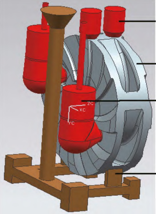
The impeller adopts a horizontal pouring position with the risers strategically placed to address thermal hot spots, such as the intersection of the rear cover plate and hub, and the blade-cover plate interfaces. The bottom risers align with two blades, efficiently feeding the hub hot spots, while the top risers, positioned at the highest blade intersection, facilitate gas venting and slag collection.
4.3. Fine-grain Strengthening
Fine-grain strengthening improves the microstructure, enhances carbide morphology, distribution, and matrix strengthening, thereby increasing impact toughness, inhibiting crack formation, and meeting the demands of abrasive conditions.
4.3.1. Chilled Sleeve for Increased Undercooling
The impeller’s torque transmission primarily occurs through the hub’s trapezoidal threads, making structural integrity crucial. A chilled sleeve, acting as an internal cold iron, is embedded within the hub to increase undercooling, promoting fine-grain strengthening. The sleeve’s wall thickness is calculated using the hot-spot circle method, ensuring complete enclosure of the threaded structure.
4.3.2. Inoculation Treatment
The pouring temperature is a crucial parameter, determined to be 1440°C ± 10°C, considering factors such as alloy composition, part structure, heat absorption during foam replacement, and riser feeding. Cerium-based rare earth is placed at the bottom of the ladle for inoculation, followed by in-stream addition of high-carbon chromium iron particles for uniform grain refinement.
5. Conclusion
By carefully selecting alloy components, controlling microstructure morphology, and adopting effective process techniques, the ultra-high chromium impeller meets the abrasion resistance requirements under acidic conditions in hydrometallurgical applications. Successfully applied in a copper-cobalt mine smelting project in the Democratic Republic of the Congo, the impeller has operated beyond the six-month contract requirement, satisfying user demands.