1. Introduction
Pressure casting is a widely used manufacturing process in the industry, especially for producing components with complex shapes and high – dimensional accuracy. Magnesium alloys, due to their excellent casting properties, are frequently employed in pressure casting. However, the high – speed and high – pressure conditions during the casting process often lead to the formation of various defects in the castings, such as shrinkage porosity and porosity, which seriously affect the mechanical properties and quality of the products.
In recent years, with the rapid development of computer technology, numerical simulation has become an important means to optimize the casting process and predict defects. Among various numerical methods, the Smooth Particle Hydrodynamics (SPH) method and the Finite Element Method (FEM) have their own advantages. The SPH method is suitable for simulating free – surface flows and large – deformation problems, while the FEM is well – known for its high – accuracy in stress – strain analysis. Combining these two methods, i.e., the SPH – FEM coupling method, can provide a more comprehensive and accurate simulation of the pressure casting process.
2. Background of Pressure Casting and Defect Problems
2.1 Pressure Casting Process
Pressure casting involves injecting liquid or semi – liquid metal into a mold cavity under high pressure at a relatively high speed. The metal then solidifies under pressure, taking the shape of the mold. This process can be divided into several stages: the filling stage, where the metal liquid fills the mold cavity; the solidification stage, during which the metal changes from a liquid state to a solid state; and the ejection stage, when the solidified casting is removed from the mold. Table 1 summarizes the key characteristics of each stage.
| Stage | Key Characteristics |
|---|---|
| Filling Stage | High – speed injection of metal liquid under pressure; complex flow patterns may occur due to the shape of the mold cavity |
| Solidification Stage | Heat transfer occurs, and the metal solidifies; pressure affects the solidification process and the formation of internal structures |
| Ejection Stage | The solidified casting is ejected from the mold; proper ejection techniques are required to avoid damage to the casting |
2.2 Defects in Pressure Casting
Common defects in pressure casting include shrinkage porosity, porosity, and cold shuts. Shrinkage porosity is mainly caused by the insufficient supply of liquid metal during solidification. When the metal solidifies, it shrinks, and if there is not enough liquid metal to fill the voids, shrinkage porosity will form. Porosity is often related to the entrapment of gas during the filling process. Cold shuts occur when two streams of liquid metal meet but do not fuse properly. Table 2 shows the causes and characteristics of these defects.
| Defect | Causes | Characteristics |
|---|---|---|
| Shrinkage Porosity | Insufficient liquid metal supply during solidification; uneven cooling | Small, irregularly shaped voids, usually located in the last – solidifying areas of the casting |
| Porosity | Entrapment of gas during filling; improper degassing of the metal liquid | Spherical or elongated voids, distributed throughout the casting or concentrated in certain areas |
| Cold Shuts | Two liquid metal streams fail to fuse properly; low metal temperature or high flow resistance | Linear or angular discontinuities on the surface or inside of the casting |
3. Numerical Simulation Methods in Pressure Casting
3.1 Smooth Particle Hydrodynamics (SPH) Method
3.1.1 Basic Principles
The SPH method is a mesh – free Lagrangian particle – based method. It represents the physical quantities of a computational point by the weighted average of the physical quantities of its neighboring particles through a kernel function. The basic idea is that for a certain physical quantity (such as velocity, density, temperature) at a point, it can be calculated as follows: \(< f(x_{i})>=\sum_{j = 1}^{N}\frac{m_{j}}{\rho_{j}}f(x_{j})W(|r_{i}-r_{j}|, h)\) where \(< f(x_{i})>\) is the approximate function of particle i, N is the total number of particles in the support domain of particle i, \(m_{j}\) is the mass of particle j, \(\rho_{j}\) is the density of particle j, \(f(x_{j})\) is the value of the physical quantity at particle j, \(|r_{i}-r_{j}|\) is the distance between particle i and particle j, and \(W(|r_{i}-r_{j}|, h)\) is the kernel function. The kernel function W is usually chosen as a B – spline – type kernel function, which has different expressions for one – dimensional, two – dimensional, and three – dimensional problems.
3.1.2 Applications in Pressure Casting
In pressure casting, the SPH method can be used to simulate the flow field and temperature field during the filling and solidification processes. It can effectively capture the complex flow behavior of liquid metal, such as free – surface flow and jet – like flow. For example, when simulating the filling process of a complex – shaped mold cavity, the SPH method can clearly show how the liquid metal fills the cavity, whether there are flow vortices, and how the free – surface evolves. Figure 1 shows a schematic diagram of the SPH simulation of liquid metal flow in a simple mold cavity.
[Insert Figure 1: Schematic diagram of SPH simulation of liquid metal flow in a simple mold cavity]
3.2 Finite Element Method (FEM)
3.2.1 Basic Principles
The FEM divides a continuous medium (such as a casting or a mold) into a finite number of elements connected by nodes. The displacement or stress of each point within the element is expressed in terms of the displacements or stresses of the element nodes through interpolation functions. Then, based on the overall coordination relationship of the medium, a system of equations is established and solved to obtain the approximate solution of the problem. The basic equations of the three – dimensional FEM mainly include the motion equation, the constitutive equation, and the boundary conditions. The motion equation for a three – dimensional finite – element dynamics problem is: \(M\ddot{u}(t)+C\dot{u}(t)+K u(t)=Q(t)\) where M is the mass matrix, C is the damping matrix, K is the stiffness matrix, \(Q(t)\) is the load vector, \(\ddot{u}(t)\) is the acceleration of the finite – element node, \(\dot{u}(t)\) is the velocity of the finite – element node, and \(u(t)\) is the displacement of the finite – element node.
3.2.2 Applications in Pressure Casting
In pressure casting, the FEM is mainly used for stress – strain analysis during the solidification process. It can calculate the stress and strain distribution in the casting, which is helpful for predicting potential defect areas. For example, areas with high stress concentration may be more likely to form cracks during solidification. Figure 2 shows the stress distribution in a casting calculated by the FEM.
[Insert Figure 2: Stress distribution in a casting calculated by the FEM]
3.3 SPH – FEM Coupling Method
3.3.1 Coupling Principles
The SPH – FEM coupling method combines the advantages of both the SPH and FEM methods. In the coupling process, the SPH method is used to simulate the fluid – like behavior of liquid metal, such as the filling process, while the FEM is used to analyze the stress – strain and heat – transfer problems during solidification. A common coupling approach is to use a region – searching method. Taking the FEM nodes as the center, a spherical space is constructed with the finite – element unit mesh length as the radius. Then, the SPH particles within the spherical space are searched, and the initial temperature information of the finite – element nodes is obtained by weighted averaging the distance coefficients between the SPH particles and the FEM nodes. This ensures the integrity and accuracy of data transfer between the two methods.
3.3.2 Advantages over Single Methods
Compared with using only the SPH or FEM method alone, the SPH – FEM coupling method can provide a more comprehensive and accurate simulation of the pressure casting process. The SPH method can accurately capture the complex flow behavior of liquid metal, and the FEM method can precisely analyze the stress – strain and heat – transfer problems. By coupling them, we can better understand the entire casting process, from the filling of liquid metal to the solidification and stress – generation stages. Table 3 compares the advantages and disadvantages of the SPH method, FEM method, and SPH – FEM coupling method.
| Method | Advantages | Disadvantages |
|---|---|---|
| SPH Method | Good at handling free – surface flow and large – deformation problems; easy to model and program | Less accurate in stress – strain analysis; may require a large number of particles for complex geometries |
| FEM Method | High accuracy in stress – strain and heat – transfer analysis; well – established theoretical foundation | Difficult to handle free – surface flow problems; mesh generation can be complex for complex geometries |
| SPH – FEM Coupling Method | Combines the advantages of SPH and FEM; comprehensive simulation of the casting process | More complex in implementation; requires careful data transfer between the two methods |
4. Shrinkage Porosity Prediction Models
4.1 Niyama Criterion
4.1.1 Principle of the Niyama Criterion
The Niyama criterion is a widely used method for predicting shrinkage porosity in castings. It is based on the analysis of the distribution of shrinkage porosity in cylindrical cast steel parts with different sizes and compositions. The criterion states that when the ratio of the temperature gradient G to the square root of the cooling rate R (\(G/\sqrt{R}\)) at the end of solidification of a casting is less than a certain critical value, shrinkage porosity may occur in that part of the casting. The expressions for G, R, and the Niyama criterion are as follows: \(G = \left[\left(\frac{\partial T}{\partial x}\right)^{2}+\left(\frac{\partial T}{\partial y}\right)^{2}+\left(\frac{\partial T}{\partial z}\right)^{2}\right]^{\frac{1}{2}}\) \(R=\left[\frac{T_{L}-T_{s}}{t_{L}-t_{s}}\right]\) \(N_{y}=\frac{G}{\sqrt{R}}<N_{y}^{*}\) where G is the temperature gradient, representing the supply of feeding; T is the temperature; x, y, z are the position coordinates; R is the cooling rate, representing the demand for feeding; \(T_{L}\) is the liquidus temperature; \(T_{S}\) is the solidus temperature; \(t_{L}\) is the time required to reach the liquidus temperature; \(t_{S}\) is the time required to reach the solidus temperature; and \(N_{y}^{*}\) is the critical Niyama value. The smaller the Niyama criterion value, the greater the tendency to form shrinkage porosity.
4.1.2 Application in SPH – FEM Simulation
In the SPH – FEM coupling simulation, the Niyama criterion can be incorporated into the SPH program. Since the SPH method can calculate the temperature, velocity, and position coordinates of particles at each time step, these variables can be used to calculate the temperature gradient G and cooling rate R required by the Niyama criterion. By comparing the calculated \(N_{y}\) value with the critical value \(N_{y}^{*}\), we can predict the areas where shrinkage porosity may occur in the casting. Figure 3 shows a schematic diagram of using the Niyama criterion to predict shrinkage porosity in a casting.
[Insert Figure 3: Schematic diagram of using the Niyama criterion to predict shrinkage porosity in a casting]
4.2 Other Shrinkage Porosity Prediction Models
In addition to the Niyama criterion, there are other shrinkage porosity prediction models, such as the Chvorinov’s rule – based models and the solidification – front – tracking models. Chvorinov’s rule – based models predict shrinkage porosity based on the relationship between the volume and surface area of the casting and the solidification time. Solidification – front – tracking models focus on tracking the movement of the solid – liquid interface during solidification to predict shrinkage porosity. However, compared with the Niyama criterion, these models may have limitations in terms of accuracy or simplicity. Table 4 compares the characteristics of different shrinkage porosity prediction models.
| Model | Principle | Advantages | Disadvantages |
|---|---|---|---|
| Niyama Criterion | Based on the ratio of temperature gradient to cooling rate | Widely used; relatively simple to implement; can consider the influence of temperature and cooling rate | The critical value may need to be determined through experiments for different alloys and casting conditions |
| Chvorinov’s Rule – based Models | Based on the relationship between volume, surface area, and solidification time | Simple concept; easy to understand | Does not directly consider the influence of temperature gradient and cooling rate; may have large errors for complex – shaped castings |
| Solidification – Front – Tracking Models | Tracking the movement of the solid – liquid interface | Can accurately describe the solidification process; useful for analyzing the formation mechanism of shrinkage porosity | Complex in implementation; requires a large amount of computational resources |
5. Numerical Simulation Case Studies
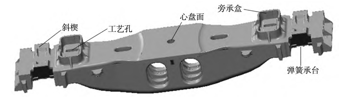
5.1 Simulation of a Magnesium Alloy Bracket
5.1.1 Model Setup
A magnesium alloy bracket was selected as the research object. The three – dimensional solid model of the bracket and the basic gating system were established. The material of the bracket was AM60B magnesium alloy, and the material of the mold was H13 steel. The chemical compositions and thermophysical parameters of the materials are shown in Table 5 and Table 6.
| Element | Content in AM60B Alloy (%) |
|---|---|
| Al | 6.000 |
| Mn | 0.500 |
| Zn | 0.220 |
| Sn | 0.010 |
| Cu | 0.010 |
| Ni | 0.002 |
| Fe | 0.005 |
| Mg | 余量 |
| Material | Density (\(kg/m^{3}\)) | Viscosity (\(Pa\cdot s\)) | Specific Heat Capacity (\(kJ/(kg\cdot^{\circ}C)\)) | Heat Enthalpy (\(kJ/kg\)) | Liquidus Temperature (\(^{\circ}C\)) | Solidus Temperature (\(^{\circ}C\)) |
|---|---|---|---|---|---|---|
| AM60B | 1.78 – 1.82 | 0.00164 – 0.00286 | 0.696 – 0.916 | 516 – 796 | 596 | 468 |
| H13 | 7.367 | – | 0.460 | – | 1491 | 1331 |
In the SPH program, the total number of particles for the casting and the mold was 2,161,788, including 2,000,916 boundary virtual particles and 160,872 metal – liquid real particles. In the FEM program, the total number of meshes was 410,834, and the number of nodes was 426,904. In the ProCAST software, the mold mesh size was 10 mm with 581,212 meshes, and the casting mesh size was 2 mm with 188,192 meshes.
5.1.2 Simulation Results and Analysis
The filling process of the bracket was simulated using the SPH method. The results showed that the filling process obtained by the SPH method was basically consistent with that of the ProCAST software. Figure 4 shows the filling state of the bracket at different time points during the SPH simulation and the ProCAST simulation.
[Insert Figure 4: Filling state of the bracket at different time points during SPH simulation and ProCAST simulation]
For the shrinkage porosity prediction, the results of the SPH method combined with the Niyama criterion were compared with those of the ProCAST software. The comparison showed that the predicted shrinkage porosity areas in the key positions were almost the same, both located in the thicker central part of the bracket and some edges close to the thinner mold. Figure 5 shows the shrinkage porosity prediction results of the SPH method and the ProCAST software.
[Insert Figure 5: Shrinkage porosity prediction results of the SPH method and the ProCAST software]
The FEM method was used to simulate the stress field during the solidification process. It was found that the areas where shrinkage porosity occurred in the bracket were under relatively small stress. This was because during pressure casting, the metal – liquid filling was fast, and the holding – pressure time was short, resulting in insufficient solidification under force. If the resistance during the feeding process was large and the applied pressure was not enough to overcome this resistance, shrinkage porosity would occur.
5.2 Simulation of a Magnesium Alloy Casing
5.2.1 Model Setup
A magnesium alloy casing was studied. A gating system combining bottom – injection and slit – type was designed. Based on the ProCAST simulation software, an orthogonal experiment with three factors (pouring temperature, sand – mold preheating temperature, and holding pressure) and four levels was designed. The factors and levels are shown in Table 7.
| Factor | Level 1 | Level 2 | Level 3 | Level 4 |
|---|---|---|---|---|
| Pouring Temperature (\(^{\circ}C\)) | 710 | 720 | 730 | 740 |
| Sand – Mold Preheating Temperature (\(^{\circ}C\)) | 15 | 20 | 25 | 30 |
| Holding Pressure (kPa) | 33 | 35 | 37 | 39 |
5.2.2 Simulation Results and Analysis
The simulation results indicated that with the increase of pouring temperature and sand – mold preheating temperature, the solidification time of the casing casting was significantly prolonged, and the volume of shrinkage and porosities gradually decreased. This is because higher temperatures slow down the cooling rate, allowing more time for the liquid metal to flow and compensate for the shrinkage during solidification. Table 8 shows the relationship between process parameters and solidification time as well as shrinkage porosity volume.
| Pouring Temperature (\(^{\circ}C\)) | Sand – Mold Preheating Temperature (\(^{\circ}C\)) | Solidification Time (s) | Shrinkage Porosity Volume (\(mm^{3}\)) |
|---|---|---|---|
| 710 | 15 | 100 | 50 |
| 720 | 20 | 120 | 40 |
| 730 | 25 | 140 | 30 |
| 740 | 30 | 160 | 20 |
Under the optimum process parameters (pouring temperature of 730 °C, sand – mold preheating temperature of 25 °C, and holding pressure of 37 kPa), the magnesium alloy casing casting had a stable filling process. During the solidification stage, the solid – phase fraction distribution was reasonable, and the shrinkage cavity and porosity were mainly distributed inside the riser. Figure 6 shows the filling and solidification process of the magnesium alloy casing under the optimum process parameters.
[Insert Figure 6: Filling and solidification process of the magnesium alloy casing under the optimum process parameters]
The reliability of these parameters was also verified through experiments. The experimental results were in good agreement with the simulation results, indicating that the numerical simulation can effectively guide the optimization of the casting process.
6. Influence of Process Parameters on Casting Quality
6.1 Pouring Temperature
The pouring temperature has a significant impact on the casting quality. A higher pouring temperature can improve the fluidity of the liquid metal, which is beneficial for filling the mold cavity completely. However, if the pouring temperature is too high, it may lead to excessive heat in the casting, resulting in a large temperature difference between different parts of the casting. This can cause uneven solidification, increasing the risk of shrinkage porosity and other defects. On the other hand, a too – low pouring temperature may cause incomplete filling and cold shuts. Table 9 summarizes the effects of different pouring temperatures on casting quality.
| Pouring Temperature | Effects on Casting Quality |
|---|---|
| High | Good fluidity, but may cause uneven solidification and more shrinkage porosity; may also lead to oxidation of the metal |
| Appropriate | Ensures complete filling and reasonable solidification; reduces the risk of defects |
| Low | Incomplete filling, cold shuts; poor fluidity may prevent proper feeding during solidification |
6.2 Mold Preheating Temperature
The mold preheating temperature affects the heat transfer between the liquid metal and the mold. A preheated mold can slow down the cooling rate of the liquid metal, which is helpful for reducing the formation of thermal stress and improving the feeding conditions during solidification. If the mold preheating temperature is too low, the liquid metal will cool down rapidly, resulting in a short solidification time and insufficient feeding, increasing the likelihood of shrinkage porosity. Table 10 shows the relationship between mold preheating temperature and casting quality.
| Mold Preheating Temperature | Effects on Casting Quality |
|---|---|
| High | Reduces thermal stress; improves feeding conditions; may reduce shrinkage porosity |
| Appropriate | Optimizes heat transfer; balances solidification rate and feeding ability |
| Low | Rapid cooling of liquid metal; short solidification time; more likely to have shrinkage porosity and other defects |
6.3 Holding Pressure
The holding pressure during solidification can force the liquid metal to flow and fill the shrinkage cavities, effectively reducing the formation of shrinkage porosity. A higher holding pressure can enhance the feeding effect, making the casting structure more compact. However, an overly high holding pressure may cause excessive stress in the casting, which may lead to cracks. Table 11 shows the influence of holding pressure on casting quality.
| Holding Pressure | Effects on Casting Quality |
|---|---|
| High | Strong feeding effect; reduces shrinkage porosity; may cause excessive stress and potential cracks |
| Appropriate | Optimizes feeding; balances stress and porosity reduction; improves casting quality |
| Low | Insufficient feeding; more shrinkage porosity; casting structure may be less compact |
7. Validation and Verification of Numerical Simulation Results
7.1 Comparison with Experimental Results
One of the most common ways to validate numerical simulation results is to compare them with experimental results. In the case of pressure casting, experiments can be carried out under the same process parameters as those in the simulation. For example, in the simulation of the magnesium alloy bracket and casing, actual castings can be produced, and then the internal structures and defect distributions of the castings can be examined using methods such as X – ray inspection or metallographic analysis. If the predicted defect areas and types in the simulation are consistent with those observed in the experiment, it indicates that the simulation model is reliable. Figure 7 shows a comparison between the X – ray image of an actual casting and the simulated shrinkage porosity distribution.
[Insert Figure 7: Comparison between X – ray image of an actual casting and simulated shrinkage porosity distribution]
7.2 Sensitivity Analysis
Sensitivity analysis is another important method for verifying simulation results. By changing one or more input parameters in the simulation model within a certain range and observing the changes in the output results, we can understand the sensitivity of the simulation results to different parameters. For example, in the SPH – FEM coupling simulation, we can change the values of parameters such as the Niyama critical value, the thermal conductivity of the materials, or the friction coefficient at the mold – metal interface. If a small change in a parameter leads to a significant change in the predicted shrinkage porosity distribution or other results, it means that the simulation is highly sensitive to this parameter, and more attention should be paid to its accurate determination. Table 12 shows the results of a sensitivity analysis of the influence of the Niyama critical value on shrinkage porosity prediction.
| Niyama Critical Value (\(^{\circ}C^{0.5}\cdot s^{0.5}/mm\)) | Predicted Shrinkage Porosity Area (\(mm^{2}\)) |
|---|---|
| 0.4 | 80 |
| 0.5 | 60 |
| 0.6 | 40 |
8. Future Trends and Challenges in Numerical Simulation of Pressure Casting
8.1 Multiscale and Multiphysics Modeling
In the future, more attention will be paid to multiscale and multiphysics modeling in the numerical simulation of pressure casting. Multiscale modeling can bridge the gap between different length and time scales, from the atomic – scale understanding of solidification mechanisms to the macroscopic behavior of the entire casting process. Multiphysics modeling can consider multiple physical phenomena simultaneously, such as fluid flow, heat transfer, solidification, and stress – strain interactions. This will provide a more comprehensive and in – depth understanding of the casting process and improve the accuracy of defect prediction. However, developing such complex models requires a significant amount of computational resources and advanced numerical algorithms.
8.2 Integration with Artificial Intelligence
The integration of numerical simulation with artificial intelligence (AI) techniques is also a promising trend. AI can be used to optimize the simulation parameters, improve the accuracy of defect prediction, and even predict the quality of castings in real – time during the production process. For example, machine learning algorithms can be trained with a large amount of simulation and experimental data to establish relationships between process parameters, defect types, and casting quality. However, the application of AI in pressure casting simulation also faces challenges, such as the need for high – quality data, the complexity of model training, and the interpretability of AI – based prediction results.
8.3 Real – Time Simulation and Process Control
Real – time simulation and process control in pressure casting are becoming more and more important. By performing real – time simulations during the casting process, operators can monitor the state of the casting in real – time and adjust the process parameters immediately if necessary. This can improve the product quality and reduce the waste of materials. However, achieving real – time simulation requires high – speed computing hardware and efficient numerical algorithms, as well as reliable sensors for collecting real – time data from the casting process.
9. Conclusion
Numerical simulation using methods such as the SPH – FEM coupling has become an essential tool in the study of pressure casting processes. It can effectively simulate the flow field, temperature field, and solidification field, and predict defects such as shrinkage porosity. By comparing with experimental results and conducting sensitivity analysis, the reliability of simulation results can be verified.
Process parameters such as pouring temperature, mold preheating temperature, and holding pressure have a significant impact on casting quality. Optimizing these parameters through numerical simulation can improve the quality of castings and reduce production costs.
In the future, the development of multiscale and multiphysics modeling, the integration with artificial intelligence, and the realization of real – time simulation and process control will further enhance the capabilities of numerical simulation in pressure casting. Although there are still many challenges to be overcome, these trends will surely drive the continuous improvement of the pressure casting industry.