
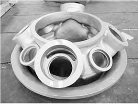
We encountered significant challenges during the trial production of a four-cylinder diesel engine cylinder block with an integrated gear chamber and cooling water pump housing. The casting, weighing 69 kg and made of HT250 gray iron, featured extreme wall thickness variations (4.5–60 mm) and elevated hot spots at the water pump housing (103 mm above the top deck) and gear chamber (130 mm above the bottom deck). Initial trials using a shell casting process (sand-coated iron mold with 6–8 mm sand layer) yielded over 60% scrap due to subsurface hole-type defects clustered around three locations near the water pump housing’s highest point. Initial defect analysis suggested gas entrapment, but conventional countermeasures failed. Structural reevaluation revealed an isolated 65 mm × 45 mm × 33 mm hot spot beneath the pump bore, surrounded by 5 mm thin walls. This created an unsupported thermal mass that solidified last, starving the overlying high-point region of liquid metal. Compounded by the shell casting‘s rapid cooling, which degraded surface-layer fluidity, the resulting pressure drop facilitated gas infiltration—forming shrinkage-blowhole hybrids.
Early gas-oriented solutions included extending core baking (reducing binder gas from 14.5 to 12–13 mL/g), adding vent pins and overflow channels, and elevating pouring temperatures from 1,420°C to 1,440°C. Despite a 1.7 m-high flame observed during pouring through auxiliary vents, defects persisted. Numerical simulations confirmed that the hot spot’s isolation prevented effective feeding. Crucially, the shell casting process inhibited vent efficacy as surface solidification trapped gases. Reclassifying the defects as shrinkage-driven required a holistic approach: increasing gating cross-sections to enhance liquid pressure and feeding, while accelerating pouring to minimize oxide formation. We derived the optimal gating ratio using flow continuity equations, where the initial cross-sectional areas ($\Sigma F_{\text{straight}}$, $\Sigma F_{\text{transverse}}$, $\Sigma F_{\text{inner}}$) followed:
$$\Sigma F_{\text{straight}} : \Sigma F_{\text{transverse}} : \Sigma F_{\text{inner}} = 1 : 1.2 : 1.4$$
Post-optimization, each element expanded by 14.8–15.1%, modifying the ratio to:
$$\Sigma F_{\text{straight}} : \Sigma F_{\text{transverse}} : \Sigma F_{\text{inner}} \approx 1.15 : 1.38 : 1.61$$
Pouring time decreased from 17 s to 12–14 s, governed by the empirical relation:
$$t = k \cdot \sqrt[3]{W}$$
where $t$ is pouring time (s), $W$ is casting weight (kg), and $k$ is a mold-type coefficient (reduced from 2.8 to 2.1 for shell casting). This yielded a 24% average velocity increase, slashing oxide content from 2.1% to 1.8%. Internal pressure rose proportionally to the square of flow velocity ($P \propto v^2$), counteracting gas infiltration. Results from 500+ castings validated the approach:
| Parameter | Initial | Optimized | Change |
|---|---|---|---|
| Gating cross-section area | Baseline | +14.8–15.1% | Increase |
| Pouring time (s) | 17 | 12–14 | ↓ 18–29% |
| Surface oxide (%) | 2.1 | 1.8 | ↓ 14.3% |
| Shrinkage-blowhole rate | >60% | 0% | Eliminated |
Key learnings emerged: First, the shell casting process demands precise thermal management, as rapid cooling impairs vent functionality and thin-wall feeding. Second, isolated hot spots in geometrically complex regions require strategic orientation—either minimized or positioned downward. Third, gating optimization must balance flow velocity and oxide control; excessive speed exacerbates turbulence, while slow pours intensify surface solidification. Our approach succeeded by integrating structural analysis with numerical simulation, proving that shrinkage mitigation in shell casting hinges on sustaining internal pressure through controlled, high-velocity filling. Future work will extend this methodology to other high-risk components like turbine housings, where similar thermal imbalances exist.