
To achieve vehicle lightweighting, we established a solid model of an aluminum alloy steering knuckle and conducted multi-condition topology optimization using the SIMP interpolation model. Combining the forming requirements of squeeze casting, we completed the structural optimization of the aluminum alloy steering knuckle. Our research demonstrates that the maximum stress experienced by the steering knuckle under various operating conditions is significantly lower than its yield limit, achieving a remarkable 60.9% mass reduction compared to ductile cast iron. After T6 heat treatment, samples extracted from the steering knuckle body exhibited an average tensile strength of 311.03 MPa, yield strength of 252.13 MPa, and elongation of 7.45%. These mechanical properties exceed specified requirements, confirming the component’s performance viability.
The steering knuckle, a critical chassis component, endures complex and diverse loads during vehicle operation, necessitating high strength and impact resistance. Traditional manufacturing predominantly employs ductile iron sand casting. However, automotive lightweighting demands have shifted material focus toward aluminum alloys. While prior studies achieved approximately 9-48% mass reduction through topology optimization, they often neglected manufacturability considerations for subsequent forming processes. Squeeze casting offers exceptional suitability for high-performance structural components like steering knuckles due to its ability to produce dense microstructures, superior mechanical properties, and high dimensional accuracy – making it an ideal process for lightweight automotive applications.
Topology Optimization Methodology
Topology optimization identifies the optimal material distribution within a defined design space to achieve the lightest structure meeting required performance criteria. We adopted the Solid Isotropic Material with Penalization (SIMP) method within the variable density approach. This method introduces a penalty factor to penalize intermediate densities, driving the solution toward a near 0-1 (void-solid) distribution. The SIMP model defines the relationship between Young’s modulus \( E \) and the element density \( \rho \) as:
$$E(\rho) = E_{\min} + \rho^p (E_0 – E_{\min})$$
where \( E_0 \) is the elastic modulus of the solid material, \( E_{\min} \) is a very small modulus assigned to void regions to prevent singularity, and \( p \) is the penalty factor (typically \( p \geq 3 \)).
Given the multi-load nature of steering knuckle operation (experiencing conditions like 4x overload, single-side bump, bump crossing, forward braking, forward acceleration), we formulated a multi-condition topology optimization problem. Assuming equal importance among the \( m \) (\( m = 5 \)) load cases, the optimization problem is mathematically expressed as:
$$
\begin{array}{ll}
\min & C(\mathbf{\rho}) = \left( \sum_{k=1}^{m} \omega_k \left( \frac{C_k(\mathbf{\rho}) – C_k^{\min}}{C_k^{\max} – C_k^{\min}} \right)^q \right)^{1/q} \\
\text{s.t.} & V(\mathbf{\rho}) / V_0 \leq f \\
& \sigma_j(\mathbf{x}) < \sigma_0 \\
& 0 < \rho_{\min} \leq \rho_e \leq 1, e=1,\ldots,N
\end{array}
$$
where \( C(\mathbf{\rho}) \) is the aggregated compliance objective function; \( C_k(\mathbf{\rho}) \) is the compliance (strain energy) for load case \( k \); \( C_k^{\max} \) and \( C_k^{\min} \) are the maximum and minimum compliances for condition \( k \) (derived from the initial solid model and a fully filled model respectively); \( \omega_k \) is the weighting factor for condition \( k \) (all \( \omega_k = 1 \)); \( q \) is the aggregation exponent (\( q = 3 \)); \( V(\mathbf{\rho}) \) and \( V_0 \) are the optimized and initial volumes; \( f = 0.3 \) is the volume fraction constraint; \( \sigma_j(\mathbf{x}) \) is the stress at node \( j \); \( \sigma_0 = 230 \text{ MPa} \) is the allowable stress; \( \rho_e \) is the density design variable for element \( e \); and \( N \) is the total number of elements.
Finite Element Modeling and Multi-Condition Analysis
Based on the existing ductile iron steering knuckle geometry and preserving all assembly interfaces, we constructed a maximum solid model of the aluminum alloy steering knuckle. This model was imported into HyperMesh for meshing, employing a global element size of 1 mm to capture critical features. The topology optimization model is depicted below, clearly showing non-designable regions (circled areas representing mating surfaces) and the design space (grey regions subject to optimization).
Material properties for the A356 aluminum alloy were defined: Elastic Modulus \( E = 72.4 \text{ GPa} \), Poisson’s ratio \( \nu = 0.33 \), Density \( \rho = 2700 \text{ kg/m}^3 \). Five critical load cases were considered, reflecting extreme driving scenarios. As the steering knuckle isn’t rigidly fixed to the vehicle body under load, the Inertia Relief Method (IRM) was applied, balancing external loads with inertial forces without constraining rigid body motion. Forces (\( F_x, F_y, F_z \)) and moments (\( T_x, T_y, T_z \)) were applied at five key connection points linked to the main structure via RBE3 spider elements:
- Wheel Center Connection Point
- Lower Control Arm Connection Point
- Tie Rod Connection Point
- Shock Absorber Connection Point
- Brake Caliper Connection Point
| Load Case Description | Connection Point Loads & Moments | |||||
|---|---|---|---|---|---|---|
| Wheel Center | Lower Control Arm | Tie Rod | Shock Absorber | Brake Caliper | ||
| 4x Overload | Fx: -472, Fy: 68, Fz: 19586, Tx: 18612, Ty: 0, Tz: 448 | Fx: 908, Fy: 5077, Fz: -1067, Tx: 0, Ty: 0, Tz: 0 | Fx: 177, Fy: 906, Fz: -178, Tx: 0, Ty: 0, Tz: 0 | Fx: -619, Fy: -6051, Fz: -18126, Tx: 885833, Ty: 103796, Tz: -81356 | Fx: 0, Fy: 0, Fz: -10, Tx: 0, Ty: 0, Tz: 0 | |
| Single-Side Bump | Fx: 9760, Fy: 18, Fz: 14702, Tx: 4439, Ty: 0, Tz: -18 | Fx: -9494, Fy: 5756, Fz: -1625, Tx: 0, Ty: 0, Tz: 0 | Fx: -269, Fy: -1683, Fz: 304, Tx: 0, Ty: 0, Tz: 0 | Fx: 4, Fy: -4091, Fz: -13166, Tx: 490924, Ty: 310901, Tz: -87463 | Fx: 0, Fy: 0, Fz: -10, Tx: 0, Ty: 0, Tz: 0 | |
| Bump Crossing | Fx: 9726, Fy: 40, Fz: 14724, Tx: 11370, Ty: 0, Tz: -21 | Fx: -6946, Fy: 7579, Fz: -1990, Tx: 0, Ty: 0, Tz: 0 | Fx: -609, Fy: -3960, Fz: 765, Tx: 0, Ty: 0, Tz: 0 | Fx: -2171, Fy: -3658, Fz: -13284, Tx: 556935, Ty: -498896, Tz: 72772 | Fx: 0, Fy: 0, Fz: -10, Tx: 0, Ty: 0, Tz: 0 | |
| Forward Braking | Fx: 12208, Fy: 125, Fz: 27741, Tx: 418772, Ty: 0, Tz: -94163 | Fx: -10829, Fy: 1502, Fz: -683, Tx: 0, Ty: 0, Tz: 0 | Fx: 73, Fy: 549, Fz: -60, Tx: 0, Ty: 0, Tz: 0 | Fx: 2331, Fy: -2042, Fz: -6066, Tx: 344352, Ty: 1088870, Tz: -208086 | Fx: -3779, Fy: -135, Fz: -20727, Tx: 95844, Ty: -1138150, Tz: -10068 | |
| Forward Acceleration | Fx: -6136, Fy: -4, Fz: 4888, Tx: -2320, Ty: 0, Tz: -60 | Fx: 8222, Fy: 1609, Fz: 551, Tx: 0, Ty: 0, Tz: 0 | Fx: -12, Fy: -60, Fz: -1, Tx: 0, Ty: 0, Tz: 0 | Fx: -2079, Fy: -1545, Fz: -5222, Tx: 243874, Ty: -779369, Tz: 112372 | Fx: 0, Fy: 0, Fz: -10, Tx: 0, Ty: 0, Tz: 0 | |
Topology Optimization Results
The optimization task minimized the aggregated multi-condition compliance, constrained by a volume fraction \( f \leq 0.3 \) and maximum stress \( \sigma_{\max} < 230 \text{ MPa} \). Bi-directional draft constraints were imposed for manufacturability. After 29 iterations, the compliance converged to a stable minimum. Setting a density threshold of 0.3, elements exceeding this value defined the retained structure.
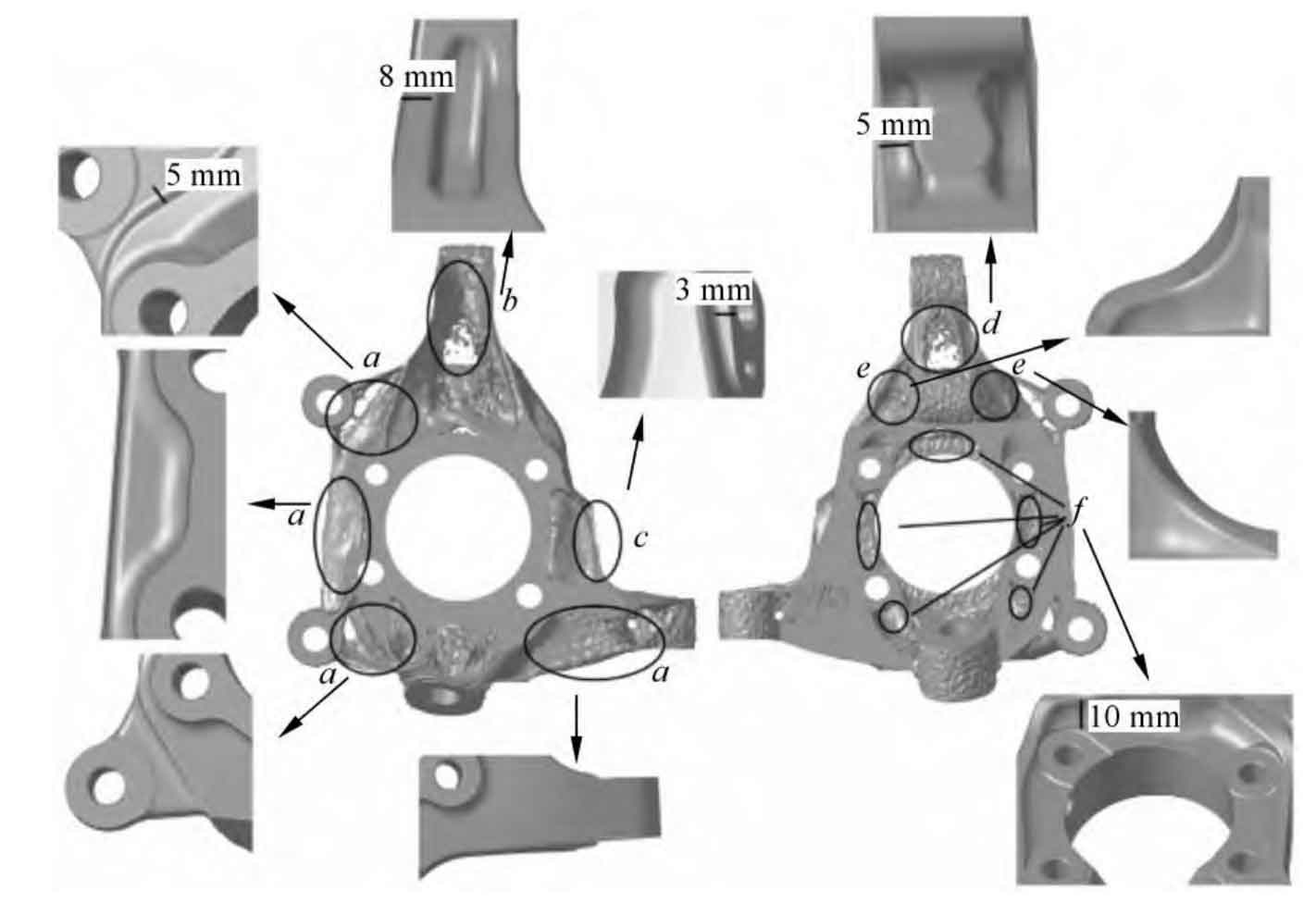
Squeeze Casting-Oriented Structural Design
The raw topology optimization result was geometrically smoothed and imported into CAD software for detailed design, incorporating specific features for squeeze casting manufacturability and performance:
- Backside Mass Reduction: The large optimized area on the back face was uniformly recessed by 5 mm. Areas surrounding the brake caliper mounting holes received an additional 5 mm recess.
- Side Slotting: To maintain strength in the deep optimized region ‘b’, material was removed via slotting approximately 8 mm from the boundary.
- Side Boss and Vent Holes: A 3 mm high boss was added to strengthen region ‘c’. A Ø10 mm through-hole and a Ø5 mm blind hole were incorporated to aid venting during squeeze casting.
- Central Mass Reduction: The heavily optimized central region ‘d’ was recessed by approximately 5 mm on both sides, maintaining strength while accommodating adjacent components.
- Shock Mount Recess: The area ‘e’ near the shock absorber mount was transformed from convex to concave.
- Front Mass Reduction: The front face ‘f’ showed significant optimization potential. A ~10 mm recess was implemented around the central hole.
Critical squeeze casting process considerations were integrated:
- Draft Angles: A minimum draft angle of 5° was applied to all relevant surfaces to ensure easy part ejection.
- Parting Line: The parting line was strategically defined based on geometry complexity and draft direction.
- Locating Features: Bosses and grooves were added to facilitate precise location during subsequent machining.
- Gating Design: For vertical squeeze casting, molten metal enters from the back towards the front. Runner ribs were designed to ensure smooth, controlled filling.
Finite Element Strength Verification
The structurally optimized aluminum steering knuckle model underwent finite element analysis under the same five load cases. Stress distributions were examined to ensure structural integrity.
| Load Case | Maximum Stress (MPa) | Requirement (MPa) |
|---|---|---|
| 4x Overload | 75.22 | ≤ 230 |
| Single-Side Bump | 161.19 | |
| Bump Crossing | 142.82 | |
| Forward Braking | 169.33 | |
| Forward Acceleration | 106.08 |
Results confirmed that the maximum stress under all conditions remained significantly below the A356-T6 yield strength (230 MPa). Stress distribution was uniform, showing no critical stress concentrations. The mass of the final aluminum design was reduced by 60.9% compared to the original ductile iron component.
Mechanical Performance Validation via Squeeze Casting
To eliminate internal segregation, refine microstructure, and enhance mechanical properties, T6 heat treatment was applied to squeeze cast steering knuckles: Solution treatment at 540°C for 6 hours, followed by quenching in 60°C water for 5 minutes, and artificial aging at 175°C for 4 hours. Tensile specimens were extracted from the knuckle body for mechanical testing.
| Property | Sample 1 | Sample 2 | Average | Requirement |
|---|---|---|---|---|
| Tensile Strength (MPa) | 316.57 | 305.49 | 311.03 | ≥ 290 |
| Yield Strength (MPa) | 256.93 | 247.33 | 252.13 | ≥ 220 |
| Elongation (%) | 8.57 | 6.32 | 7.45 | ≥ 6 |
The squeeze cast and T6 heat-treated aluminum steering knuckle comfortably exceeded all specified mechanical property requirements, validating the success of the combined topology optimization and squeeze casting approach for producing high-performance lightweight components.
Conclusion
- We established a mathematical model for steering knuckle topology optimization based on the variable density method. Utilizing HyperMesh, we performed static multi-condition topology optimization on the maximum solid model. The compliance objective converged to a stable minimum after 29 iterations.
- Based on the topology optimization results, we redesigned the steering knuckle structure, incorporating essential features for squeeze casting manufacturability (draft angles, parting line, vents, gating ribs). Finite element analysis confirmed that the maximum stress under all critical operating conditions remained significantly below the material’s yield strength, achieving a 60.9% mass reduction compared to the ductile iron baseline.
- Squeeze cast steering knuckles subjected to T6 heat treatment exhibited excellent mechanical properties: average tensile strength of 311.03 MPa, yield strength of 252.13 MPa, and elongation of 7.45%. All values surpassed the specified requirements, confirming the component’s suitability for automotive application. This study demonstrates the efficacy of integrating topology optimization with squeeze casting for developing high-performance, lightweight aluminum steering knuckles.