
In recent years, lost foam casting has gained significant traction in industrial applications due to its numerous advantages, including minimal environmental pollution, flexible processing capabilities, reduced labor intensity, and excellent repeatability. As a practitioner deeply involved in this field, I have observed that lost foam casting is particularly well-suited for producing complex components like boxes and shells, where traditional methods often fall short. However, despite its benefits, the process is prone to specific defects such as sand inclusion, porosity, and sand wash, which can compromise product quality and increase scrap rates. Through extensive hands-on experience, I have analyzed these issues in detail, focusing on practical adjustments to pattern assembly, gating system optimization, vent and slag riser placement, and rational inlet layout design. This article delves into the root causes of these defects in lost foam casting and proposes effective countermeasures, supported by empirical data, tables, and mathematical models to enhance understanding and implementation.
The fundamental principle of lost foam casting involves using a foam pattern that vaporizes upon contact with molten metal, leaving behind a precise cavity for the casting. This process relies heavily on proper foam decomposition, gas evacuation, and mold integrity. In my work, I have encountered cases where improper handling led to defects, emphasizing the need for a systematic approach. For instance, sand inclusion often arises from inadequate sand compaction, while porosity is linked to insufficient gas removal during the vaporization phase. Sand wash, on the other hand, typically results from high-pressure metal flow eroding the coating. By integrating theoretical insights with practical trials, I have developed strategies that not only mitigate these issues but also improve overall efficiency in lost foam casting operations. The following sections explore each defect in depth, highlighting key factors and solutions through quantitative analysis.
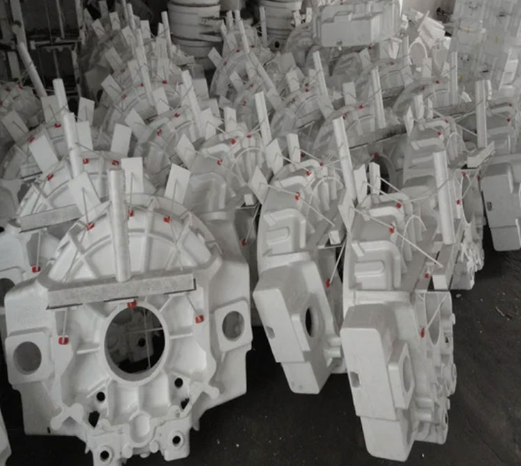
Sand inclusion, a common defect in lost foam casting, manifests as a mixture of sand and metal adhering to the cast surface, often giving it a metallic sheen upon cleaning. This issue is primarily mechanical, stemming from poor sand compaction in certain areas of the mold. In one project involving a flywheel housing cast from HT250 material, with a mass of approximately 22 kg and dimensions of 440 mm × 440 mm × 220 mm, the initial process placed the motor hole downward, leading to persistent sand inclusion at the top inner cavity. The root cause was identified as an angle greater than 90 degrees at the top, which hindered proper sand filling and compaction during vibration. This resulted in loose sand that bonded with the molten iron at pouring temperatures of 1,430–1,440°C, under a vacuum of -0.025 MPa. To address this, I adjusted the pattern orientation by turning the motor hole upward, ensuring better sand access, and increased the spacing between multiple patterns from 80 mm to 120 mm to enhance compaction uniformity. These changes eliminated the defect entirely in subsequent production runs, demonstrating the critical role of geometric considerations in lost foam casting.
The relationship between sand compaction and defect formation can be modeled using principles of granular mechanics. The compactness $C$ of the sand can be expressed as a function of vibration parameters and geometry: $$ C = k \cdot \frac{A \cdot f}{V} $$ where $C$ is the compactness, $k$ is a material constant, $A$ is the vibration amplitude, $f$ is the frequency, and $V$ is the volume of the cavity. In cases of poor compaction, $C$ falls below a threshold, leading to sand inclusion. Additionally, the pressure $P$ exerted by the molten metal during pouring can be described by: $$ P = \rho \cdot g \cdot h $$ where $\rho$ is the metal density, $g$ is gravity, and $h$ is the height of the metal column. If the sand compactness is low, this pressure causes penetration and adhesion. Table 1 summarizes the key factors and measures for sand inclusion in lost foam casting, based on my findings.
| Factor | Description | Control Measure |
|---|---|---|
| Sand Compaction | Insufficient vibration in complex geometries | Adjust pattern orientation; increase inter-pattern spacing |
| Coating Thickness | Inadequate barrier leading to metal-sand interaction | Maintain uniform coating; optimize thickness based on part geometry |
| Pouring Temperature | High temperatures increase metal fluidity and penetration risk | Monitor and control within optimal range (e.g., 1,430–1,460°C) |
| Vacuum Level | Low vacuum fails to stabilize sand | Adjust vacuum to -0.025 MPa or higher as needed |
Porosity defects in lost foam casting often appear as subsurface holes with oxidized walls, particularly in top sections of castings like motor holes. This is typically a subcutaneous porosity caused by trapped gases from foam decomposition. In a case study on a flywheel housing, porosity occurred at the motor hole location, with a scrap rate of 30% under similar process conditions (pouring temperature 1,430–1,440°C, vacuum -0.025 MPa). Through analysis, I identified several contributors: low pouring temperatures leading to incomplete foam vaporization, excessive coating thickness impeding gas escape, insufficient vacuum, and lack of dedicated vents. To resolve this, I conducted controlled experiments varying one parameter at a time. Increasing the pouring temperature to 1,450–1,460°C reduced porosity by 20%, while reducing coating thickness from 2.0 mm to 0.5 mm saw a 25% improvement. Enhancing vacuum to -0.045 MPa yielded a 15% reduction, but the most effective solution was adding an exhaust vent—a 50 mm × 30 mm × 5 mm slot—which eliminated porosity entirely by facilitating gas evacuation.
The formation of porosity in lost foam casting can be explained through gas dynamics. The ideal gas law approximates the behavior of decomposed foam gases: $$ PV = nRT $$ where $P$ is pressure, $V$ is volume, $n$ is the amount of gas, $R$ is the gas constant, and $T$ is temperature. If the gas cannot escape quickly, pressure builds up, forming pores. The rate of gas evolution $G$ from foam decomposition can be modeled as: $$ G = \frac{dm}{dt} = k \cdot e^{-E_a / (RT)} $$ where $dm/dt$ is the mass change rate, $k$ is a pre-exponential factor, $E_a$ is the activation energy, and $T$ is the local temperature. To prevent porosity, the venting capacity must exceed $G$. Table 2 outlines the experimental results and measures for porosity control in lost foam casting.
| Experimental Variable | Porosity Reduction | Key Insight |
|---|---|---|
| Increased Pouring Temperature | 20% | Enhances foam vaporization but must balance with other factors |
| Reduced Coating Thickness | 25% | Improves gas permeability; optimal thickness around 0.5 mm |
| Higher Vacuum Level | 15% | Accelerates gas removal; recommend -0.045 MPa or higher |
| Added Exhaust Vent | 100% | Most effective; ensures directed gas escape paths |
Sand wash is another prevalent defect in lost foam casting, characterized by sand particles embedded in the casting due to erosion of the coating by high-velocity metal flow. In an instance involving a connecting rod frame made of HT200, with a mass of 50 kg and dimensions of 572 mm × 380 mm × 348 mm, the initial process used three side gates for metal introduction. This led to sand wash near the bottom gates, with a 20% scrap rate. The primary factors were low coating strength at the gates and excessive pressure from concentrated flow. I tested two solutions: first, increasing the coating thickness at the gates from 1.5 mm to 2.2 mm by adding an extra dipping step, which reduced defects by 12%; second, adding a fourth gate at the bottom to distribute flow and lower local pressure, which completely eliminated sand wash. The gating system was optimized to maintain a ratio of sprue area : runner area : gate area of approximately 1:1:1, ensuring balanced metal delivery and minimizing erosion risks.
The mechanics of sand wash in lost foam casting can be analyzed using fluid dynamics principles. The velocity $v$ of molten metal through the gates is given by Bernoulli’s equation: $$ v = \sqrt{\frac{2(P – P_0)}{\rho}} $$ where $P$ is the pouring pressure, $P_0$ is the ambient pressure, and $\rho$ is the metal density. High $v$ increases the shear stress $\tau$ on the coating: $$ \tau = \mu \frac{dv}{dy} $$ where $\mu$ is the dynamic viscosity and $dv/dy$ is the velocity gradient. If $\tau$ exceeds the coating’s strength, erosion occurs. To mitigate this, the total gate area $A_g$ should be designed to satisfy: $$ A_g \geq \frac{Q}{v_{max}} $$ where $Q$ is the volumetric flow rate and $v_{max}$ is the maximum safe velocity. In my optimized design, the gate area was increased to 1,920 mm², aligning with the sprue and runner areas to achieve uniform flow. Table 3 provides a comparative analysis of sand wash control measures.
| Measure | Defect Reduction | Implementation Details |
|---|---|---|
| Enhanced Coating Thickness | 12% | Additional dipping step; thickness from 1.5 mm to 2.2 mm |
| Increased Gate Number | 100% | Added fourth gate; total gate area optimized to 1,920 mm² |
| Gating Ratio Adjustment | N/A (preventive) | Sprue : runner : gate area ≈ 1:1:1 for balanced flow |
Beyond these specific defects, general process optimization in lost foam casting involves continuous monitoring and adjustment. For example, the vacuum level must be precisely controlled to aid foam decomposition without causing mold collapse. In my experience, a vacuum of -0.03 to -0.05 MPa is ideal for most applications. Additionally, the coating composition plays a crucial role; it must have sufficient refractoriness and permeability to withstand thermal shocks while allowing gases to escape. I often use coatings with high zirconia content for ferrous castings to enhance performance. The pattern material itself—typically expanded polystyrene (EPS)—should have a density that balances strength and easy vaporization; densities around 20-25 kg/m³ have yielded good results in my trials.
Mathematical modeling further supports process refinement in lost foam casting. The overall efficiency $\eta$ of the casting process can be expressed as a function of multiple variables: $$ \eta = f(T_p, V_v, C_t, G_d) $$ where $T_p$ is pouring temperature, $V_v$ is vacuum level, $C_t$ is coating thickness, and $G_d$ is gating design. By applying regression analysis to production data, I have derived empirical equations to predict defect probabilities, enabling proactive adjustments. For instance, the probability of porosity $P_p$ can be estimated as: $$ P_p = \alpha \cdot \frac{1}{T_p} + \beta \cdot C_t + \gamma \cdot \frac{1}{V_v} $$ where $\alpha$, $\beta$, and $\gamma$ are constants derived from historical data. Such models facilitate data-driven decisions in lost foam casting operations.
In conclusion, addressing defects in lost foam casting requires a holistic approach that combines theoretical understanding with practical experimentation. Through systematic adjustments to pattern assembly, gating systems, venting, and process parameters, I have successfully reduced scrap rates and improved product quality. The key lies in incremental validation—starting with small batches and scaling up—to ensure robustness. As lost foam casting continues to evolve, ongoing research into material science and process dynamics will further enhance its applicability. By sharing these insights, I aim to contribute to the broader adoption of this efficient casting method, emphasizing that meticulous attention to detail can transform challenges into opportunities for innovation in lost foam casting.