
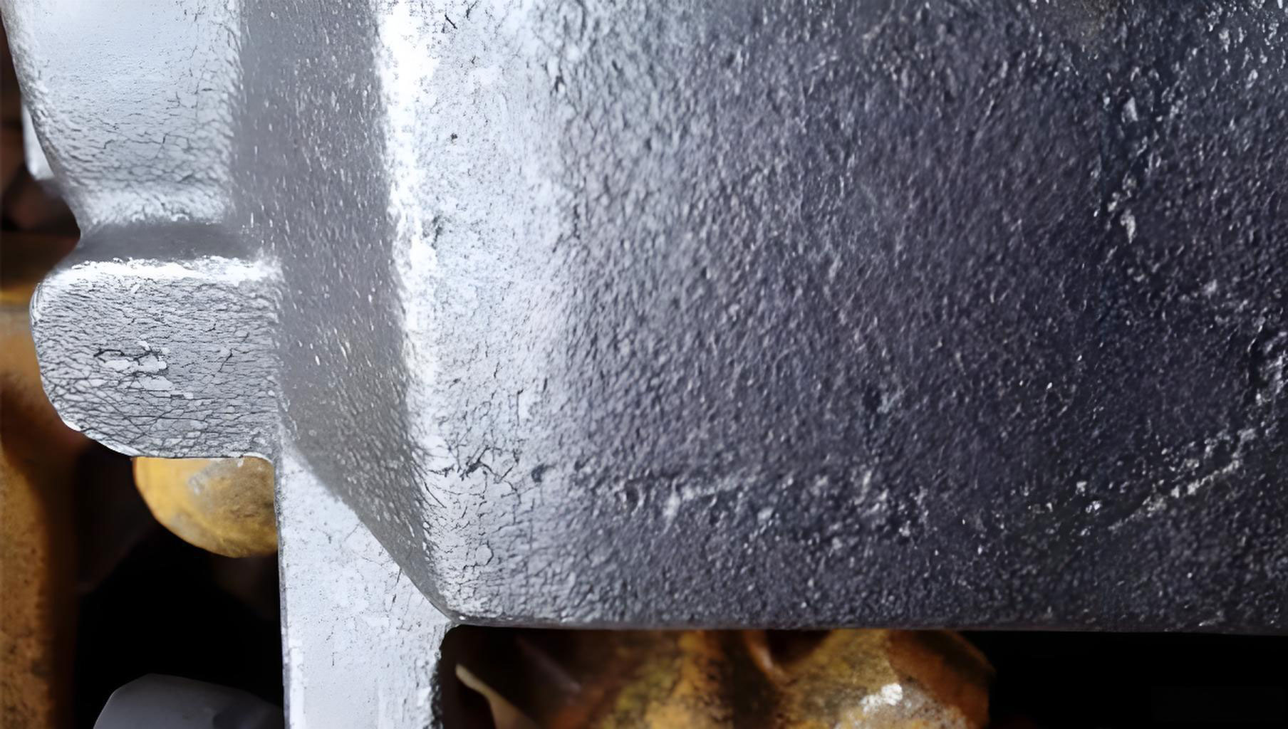
In the production of large, high-integrity castings, the battle against internal defects is a constant engineering challenge. My experience in overseeing the manufacture of a major diesel engine cylinder block, a component exceeding 7.5 tons with intricate internal passages and stringent radiographic inspection requirements, underscored this reality. The initial production runs were plagued by a persistent issue: sand inclusions, or ‘casting holes’, in critical areas like the water jacket cores. These casting holes are not merely surface imperfections; they are volumetric defects where loose or eroded sand becomes entrapped within the metallic matrix, severely compromising the pressure integrity and machinability of the final part. This account details the systematic investigation and multi-faceted engineering solutions implemented to virtually eliminate this costly defect.
The component in question was a cylinder block for a high-horsepower locomotive engine. Its geometry was formidable: nearly 4 meters in length, with wall thicknesses ranging from 14 mm to over 200 mm. The internal cavity, forming the camshaft galleries, coolant passages, and crankcase, was so complex that it necessitated a fully core-assembled mold using furan resin-bonded sand. The quality standard was exacting, requiring Level II radiographic inspection per ASTM standards on heavily loaded sections like the main bearing caps. The initial foundry process utilized a step-gating system to fill the massive mold cavity. However, despite this sound overall approach, the finished castings revealed troublesome sand inclusions at specific, repeatable locations within the upper regions of the water jacket.
The recurrence of defects in the same zones pointed not to random contamination but to systematic weaknesses in the core assembly process. A thorough failure analysis, tracing the journey of each sand core from shooting to closing of the mold, identified three primary root causes for the creation of loose sand that led to these casting holes:
- Poor Core Parting Design: The interface between the camshaft gallery core and adjacent oblong-hole cores created sharp, fragile sand corners. During the handling and placement of these heavy cores, these thin sections were prone to breakage. The resulting debris would fall into the deepest, most inaccessible part of the mold cavity, perfectly positioned to create a sand inclusion in the cast water jacket.
- Absence of Protective Features: The assembly process involved stacking large cores into a precise 3D puzzle. The square window openings on the main V-shaped core and the mating edges of the upper side cores were contact points with high risk of abrasion. As cores were lowered into position, they could rub against each other, scraping off cured sand. Furthermore, core prints (the locating pads on the core) lacked dedicated reservoirs to catch this incidental debris or spillage from coating operations.
- Inadequate Cavity Protection & Cleaning Access: Once the core assembly was complete, the open mold cavity was exposed to the foundry environment for hours during subsequent operations like coating touch-ups and gagering. This allowed ambient dust and fall-in from overhead structures to contaminate the cavity. Moreover, the design of some core prints made it impossible to visually inspect or effectively blow out sand from certain recessed areas before the final mold closure.
The strategy to eradicate these casting holes had to address every stage of sand introduction, from its generation to its potential entrapment. The solutions were rooted in robust design-for-manufacturability principles, procedural control, and simple but effective containment.
1. Core Design Optimization: Eliminating the Source
The first line of defense was to redesign the cores to be inherently more robust and less likely to generate loose sand. The parting line between the camshaft gallery core and the oblong-hole core was modified. The sharp, re-entrant corner was eliminated by incorporating a generous radius on the oblong-hole core. This transformed a fragile knife-edge of sand into a durable, rounded feature with significantly higher resistance to chipping. The fundamental strength of a resin sand core can be related to its geometry and binder properties. The stress on a sharp corner versus a radius can be conceptualized by the stress concentration factor, $K_t$.
For a sharp re-entrant corner, $K_t$ can be very high, dramatically reducing the effective strength. By introducing a radius $r$, we reduce this factor, making failure less likely. While the exact value depends on the specific geometry, the principle is that the fracture probability $P_f$ of a core feature is inversely related to its radius and the core’s tensile strength $\sigma_c$.
$$ P_f \propto \frac{1}{r \cdot \sigma_c} $$
Thus, increasing $r$ directly decreases the probability of creating sand debris that leads to casting holes.
2. Incorporation of Defensive Geometric Features
Recognizing that some handling contact is inevitable, the core patterns were modified to include passive defensive features. These did not change the functional casting geometry but profoundly impacted mold hygiene.
- Anti-Squeeze Rings: Small, raised ribs (approximately 2-3 mm high and wide) were added around the perimeter of the V-core’s window openings and along the critical mating edges of the upper side cores. These rings acted as sacrificial contact points. When cores were aligned and lowered, these rings made first contact, preventing the more critical vertical walls from rubbing and scraping. Any minor damage was confined to the ring, which was part of the core print area and not reflected in the casting.
- Integrated Sand Collection Pits: The core prints on the drag portion of the mold for the V-core and front/rear end cores were redesigned. Instead of flat seats, they now featured shallow recessed moats or pits surrounding the main locating pad. Any sand debris generated during core setting, spillage from coating, or falling from adjacent cores would naturally collect in these pits, safely away from the main cavity. The volume of such a pit $V_{pit}$ needed to be sufficient to capture potential debris, a function of the core print perimeter $P$ and the estimated debris layer thickness $d$.
$$ V_{pit} \geq P \cdot d \cdot L_{effective} $$
Where $L_{effective}$ is the length over which debris is likely to be generated. This simple containment strategy was arguably the most effective single change in preventing loose sand from reaching areas where it could form casting holes.
| Core Area | Problem | Design Solution | Mechanism |
|---|---|---|---|
| Oblong-Hole / Camshaft Interface | Sharp, fragile sand corners | Added large radius fillets | Reduces stress concentration, prevents chipping |
| V-Core Window Openings | Abrasion during side-core insertion | Added anti-squeeze rings | Provides sacrificial contact point, protects cavity walls |
| Upper Side Core Edges | Mutual abrasion during stacking | Added anti-squeeze rings | Prevents sand scraping at mating surfaces |
| Core Print Seats (V-Core, End Cores) | Nowhere for loose sand to go | Added perimeter collection pits | Traps debris safely outside the casting cavity |
3. Process and Procedural Controls
Even with perfect cores, process discipline is essential to prevent casting holes. We implemented a series of controls covering the entire workflow from core shop to mold closure.
- Core Print & Cavity Access Redesign: The front core print was redesigned to allow direct sight lines and tool access into the deepest sections of the mold cavity. This enabled operators to visually verify cleanliness and use air lances to remove any debris confidently.
- Pre-Set Core Quality Standard: A formal check was instituted prior to core setting. Every core required inspection for surface flaws: loose sand grains, damaged edges, flaking coating, or excess core flash. Cores failing this “cleanliness standard” were rejected or required repair before being allowed near the mold assembly area. The goal was “zero contaminant introduction.”
- Mandatory Cavity Covers: A simple, low-tech solution with a high impact: the use of durable plastic sheeting. Whenever work on the mold assembly was paused—whether for a break, shift change, or overnight—the entire cavity was immediately covered with plastic. This formed a physical barrier against airborne dust, accidental drops from tools, and fallout from the foundry structure. The effectiveness of this barrier in reducing contaminant influx $C_{in}$ can be modeled as a filtering efficiency $\eta$.
$$ C_{in,\;covered} = (1 – \eta) \cdot C_{in,\;open} $$
Where $\eta$ for a simple plastic cover can approach 1 for large particulate matter, the primary cause of casting holes.
- Specialized Cleaning Tools: Custom-made, flexible air blow pipes with angled nozzles were fabricated. These allowed operators to reach and thoroughly clean the newly designed collection pits and other complex geometries, ensuring any collected sand was removed from the mold entirely before closing.
| Process Stage | Control Measure | Purpose |
|---|---|---|
| Core Preparation | Pre-set visual & tactile inspection | Prevent defective or contaminated cores from entering mold |
| Mold Assembly (Downtime) | Plastic sheeting over cavity | Barrier against environmental fall-in |
| Final Mold Preparation | Use of specialized angled air lances | Positive cleaning of collection pits and blind cavities |
| Final Inspection | Flashlight inspection of key cavities prior to close | Final verification of cavity cleanliness |
4. Validation and Broader Engineering Principles
The cumulative effect of these design and process changes was validated through sustained production. Over a run of more than 600 cylinder blocks produced following the implementation of the full protocol, the scrap rate attributable to sand inclusions fell to less than 0.3%. The two occurrences that did happen were traced to specific, isolated lapses in procedure, confirming the effectiveness of the system when followed.
This case study reinforces several universal principles in combating casting holes in complex core assemblies:
- Design for Robustness First: The core geometry must be designed to survive the handling and assembly process. Sharp corners and thin sections are failure points that become internal defect sources.
- Design for Cleanability: The mold assembly must provide clear access and natural collection points for debris. Features like collection pits are a form of “error-proofing” (poka-yoke) in geometric form.
- Containment is Critical: Managing loose sand is as important as trying to prevent it. Contain it at the source (collection pits), and shield the cavity from external sources (covers).
- Process Controls are Non-Negotiable: Even the best design requires disciplined execution. Standards for core quality, cleaning procedures, and cavity protection must be explicit and audited.
The economic and qualitative impact of solving the casting holes issue was profound. Beyond the direct reduction in scrap cost and improvement in delivery reliability, it significantly enhanced the confidence in the product’s performance. The elimination of these random internal defects ensured consistent pressure tightness in the cooling system and eliminated catastrophic tool damage during machining, providing a stable, high-quality component for a critical powertrain application. The solutions, while developed for a specific large casting, are fundamentally scalable and applicable to any precision sand casting process where the integrity of the internal cavity is paramount.