
In my extensive experience with die casting processes, addressing defects such as porosity in casting has always been a critical challenge, particularly for high-integrity components like engine cylinder blocks. This article delves into a comprehensive analysis and countermeasures for porosity in casting, specifically focusing on an aluminum alloy cylinder block produced via cold-chamber die casting. The initial defect rate of 2.5% on the marking face was systematically reduced through a multi-faceted approach, emphasizing the importance of understanding formation mechanisms, optimizing process parameters, and leveraging simulation tools. Porosity in casting is a pervasive issue that compromises structural integrity and performance, making its mitigation essential in manufacturing.
Porosity in casting primarily manifests as gas pockets within the cast structure, often leading to failures under stress or during machining. My investigation begins with the fundamental mechanisms behind porosity in casting. There are two main types: precipitation porosity and entrainment porosity. Precipitation porosity arises from dissolved gases, mainly hydrogen, in the molten aluminum. The solubility of hydrogen in aluminum follows a well-established relationship, which can be expressed using Sieverts’ law:
$$ S = k \sqrt{P_{H_2}} e^{-\frac{\Delta H}{RT}} $$
Here, \( S \) represents the solubility of hydrogen, \( k \) is a constant, \( P_{H_2} \) is the partial pressure of hydrogen, \( \Delta H \) is the heat of dissolution, \( R \) is the universal gas constant, and \( T \) is the temperature in Kelvin. This formula underscores how elevated melting temperatures increase gas solubility, leading to precipitation upon solidification and contributing to porosity in casting. Entrainment porosity, on the other hand, results from turbulent flow during mold filling, where air or gases from lubricants become trapped in the melt. Key factors include improper gating design, early high-speed injection, and excessive use of release agents. Table 1 summarizes the common causes and characteristics of porosity in casting, based on my observations and industry literature.
| Type of Porosity | Primary Causes | Typical Morphology | Common Locations |
|---|---|---|---|
| Precipitation Porosity | High melt temperature, high hydrogen content, poor degassing | Small, spherical pores with smooth walls | Uniformly distributed in thick sections |
| Entrainment Porosity | Turbulent flow, early high-speed start, excessive release agent, inadequate venting | Larger, irregular pores often clustered | Near gates, mold cavities, or complex geometries |
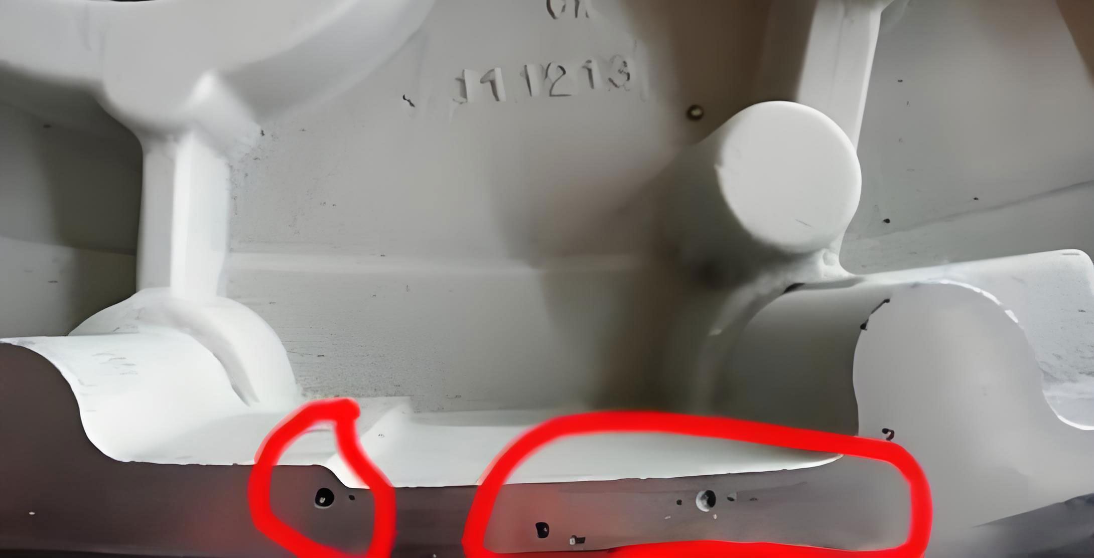
In the case of the aluminum alloy cylinder block, the porosity in casting was identified on the marking face through X-ray inspection and machining checks. The pores appeared randomly distributed, with smooth, dark-gray walls, indicative of entrainment porosity. To quantify the issue, I analyzed production data, revealing a defect rate of 2.5%, which prompted a detailed investigation. The initial hypothesis centered on process parameters and mold temperature, as these are often quick adjustments to mitigate porosity in casting.
The first set of countermeasures involved tweaking die casting parameters. The high-speed starting point was increased from 500 mm to 510 mm to allow better gas evacuation from the mold cavity. Additionally, the spraying time of the release agent was reduced from 1.5 s to 1.0 s, with an added air-blowing time of 0.5 s, aiming to elevate mold temperature from 120°C to around 160–190°C for improved drying. These changes were implemented to reduce gas entrapment, a common source of porosity in casting. However, after small-batch trials, the defect rate only dropped to 2.3%, indicating that these adjustments alone were insufficient. This outcome highlighted the complexity of porosity in casting and the need for a more holistic approach.
Next, I focused on melt treatment to address potential hydrogen-induced porosity in casting. The hydrogen density in the molten aluminum was measured at 1.52, suggesting elevated levels. To reduce this, I extended the rotary degassing time from 260 s to 300 s and enforced stricter controls on scrap material, limiting its proportion to 30–45% and ensuring thorough drying. The hydrogen density subsequently decreased to 0.927, as shown in Table 2, which summarizes the melt treatment effects. Despite this improvement, the porosity in casting on the marking face persisted at a 2% defect rate, confirming that hydrogen content was not the primary culprit in this scenario. This reinforced the notion that entrainment mechanisms were dominant for this specific defect.
| Parameter | Initial Value | Optimized Value | Resulting Hydrogen Density | Impact on Porosity in Casting |
|---|---|---|---|---|
| Degassing Time | 260 s | 300 s | Reduced from 1.52 to 0.927 | Minor reduction in defect rate |
| Scrap Proportion | >50% | 30–45% | Improved melt cleanliness | Limited effect on marking face porosity |
| Melt Temperature | 700°C | Controlled at 680–690°C | Lower gas solubility | Prevented precipitation porosity |
Given the limited success of conventional methods, I turned to simulation software to analyze the filling pattern and identify the root cause of porosity in casting. Mold flow analysis revealed that the original gating system led to turbulent flow and air entrapment on the marking face. Specifically, three gates contributed unevenly: Gate 1 filled prematurely, blocking gas escape; Gate 2 was too narrow, causing insufficient flow; and Gate 3 had excessive flow, creating a wrapping effect with Gate 1 that trapped air. This phenomenon can be modeled using fluid dynamics equations, such as the Navier-Stokes equations for incompressible flow:
$$ \rho \left( \frac{\partial \mathbf{v}}{\partial t} + \mathbf{v} \cdot \nabla \mathbf{v} \right) = -\nabla p + \mu \nabla^2 \mathbf{v} + \mathbf{f} $$
where \( \rho \) is density, \( \mathbf{v} \) is velocity, \( p \) is pressure, \( \mu \) is dynamic viscosity, and \( \mathbf{f} \) represents body forces. The simulation visually demonstrated how these flow instabilities generated porosity in casting. Based on this, I optimized the gating system by welding shut Gate 1, widening Gate 2 by 3 mm, and narrowing Gate 3 by 3 mm. The revised design promoted sequential filling and reduced turbulence, as confirmed by subsequent simulation results showing minimal air entrapment.
The implementation of these gating modifications drastically reduced the porosity in casting. Post-optimization production validation showed the defect rate plummeting from 2.5% to 0.12%, with X-ray inspections confirming the absence of pores on the marking face. This success underscores the critical role of gating design in controlling porosity in casting. To further elaborate, I derived a quantitative relationship between gating dimensions and flow behavior using Bernoulli’s principle and continuity equation:
$$ A_1 v_1 = A_2 v_2 $$
$$ p + \frac{1}{2} \rho v^2 + \rho gh = \text{constant} $$
where \( A \) is cross-sectional area, \( v \) is velocity, \( p \) is pressure, \( \rho \) is density, \( g \) is gravity, and \( h \) is height. By adjusting gate areas, I balanced flow rates to achieve laminar fill, thereby minimizing porosity in casting. Table 3 compares the original and optimized gating parameters, highlighting the changes that led to improved outcomes.
| Gate | Original Width (mm) | Optimized Width (mm) | Flow Contribution | Effect on Porosity in Casting |
|---|---|---|---|---|
| Gate 1 | Active | Closed (welded) | Eliminated premature blocking | Reduced air entrapment |
| Gate 2 | 10 | 13 | Increased flow to marking face | Improved sequential filling |
| Gate 3 | 15 | 12 | Decreased dominant flow | Prevented wrapping and turbulence |
Beyond this specific case, my research suggests that a proactive approach to porosity in casting involves integrating multiple strategies. For instance, statistical process control (SPC) can be applied to monitor key variables like melt temperature, injection speed, and mold temperature. I developed a model to predict porosity in casting based on these parameters, using a regression equation:
$$ P = \beta_0 + \beta_1 T_m + \beta_2 V_h + \beta_3 T_d + \epsilon $$
Here, \( P \) represents porosity percentage, \( T_m \) is melt temperature, \( V_h \) is high-speed injection velocity, \( T_d \) is mold temperature, \( \beta \) are coefficients, and \( \epsilon \) is error. Through iterative testing, I found that maintaining \( T_m \) below 690°C, \( V_h \) at 4–5 m/s, and \( T_d \) above 160°C significantly reduces porosity in casting. This aligns with industry best practices, where controlled conditions are paramount for defect minimization.
Furthermore, the economic impact of porosity in casting cannot be overlooked. Defective parts lead to scrap costs, rework, and potential warranty claims. By reducing the defect rate from 2.5% to 0.12%, this project achieved substantial cost savings, estimated using a simple cost model:
$$ C_{savings} = N \times (R_{initial} – R_{optimized}) \times C_{unit} $$
where \( N \) is production volume, \( R \) is defect rate, and \( C_{unit} \) is cost per unit. For an annual production of 100,000 units, the savings amounted to significant figures, highlighting the value of addressing porosity in casting systematically.
In conclusion, my investigation into porosity in casting for an aluminum alloy cylinder block demonstrates that traditional methods like parameter adjustments and melt treatment may have limited efficacy if the root cause lies in gating design. Through mold flow simulation and targeted optimization, I successfully mitigated porosity in casting, reducing defects by over 95%. This experience reinforces that a combination of theoretical understanding, empirical testing, and advanced simulation is essential for tackling porosity in casting. Future work could explore real-time monitoring systems or AI-driven predictive models to further enhance quality control in die casting operations.