
In modern manufacturing, the lost foam casting process stands out as a transformative technology, particularly for complex components like engine cylinder blocks. As a researcher deeply involved in advancing foundry techniques, I have explored the application of this process through computational simulation and hands-on production. The lost foam casting process eliminates the need for traditional cores, reduces machining allowances, and minimizes environmental impact, making it a near-net-shape and clean production method. This article delves into a comprehensive analysis of the lost foam casting process for an HT250 gray iron engine cylinder block, integrating ProCAST simulations with practical trials to optimize critical parameters such as pouring temperature, vacuum pressure, and coating thickness. The goal is to achieve defect-free castings with dense microstructure and leak-free internal passages, essential for maritime engine applications.
The engine cylinder block under study, with external dimensions of 1225 mm × 800 mm × 680 mm and a mass of 638.2 kg, presents significant challenges due to its intricate internal cavities, varying wall thicknesses (minimum 9 mm), and large surface areas with protrusions and curves. The lost foam casting process is ideally suited for such geometries, as it allows for the direct use of expandable polystyrene (EPS) foam patterns to form complex shapes without core assembly. However, the process requires meticulous design to prevent defects like shrinkage porosity, slag inclusions, and incomplete filling. To address this, we adopted a middle-gated gating system with a vertical sprue, horizontal runners, and multiple ingates to ensure steady metal flow and reduce turbulence during mold filling.
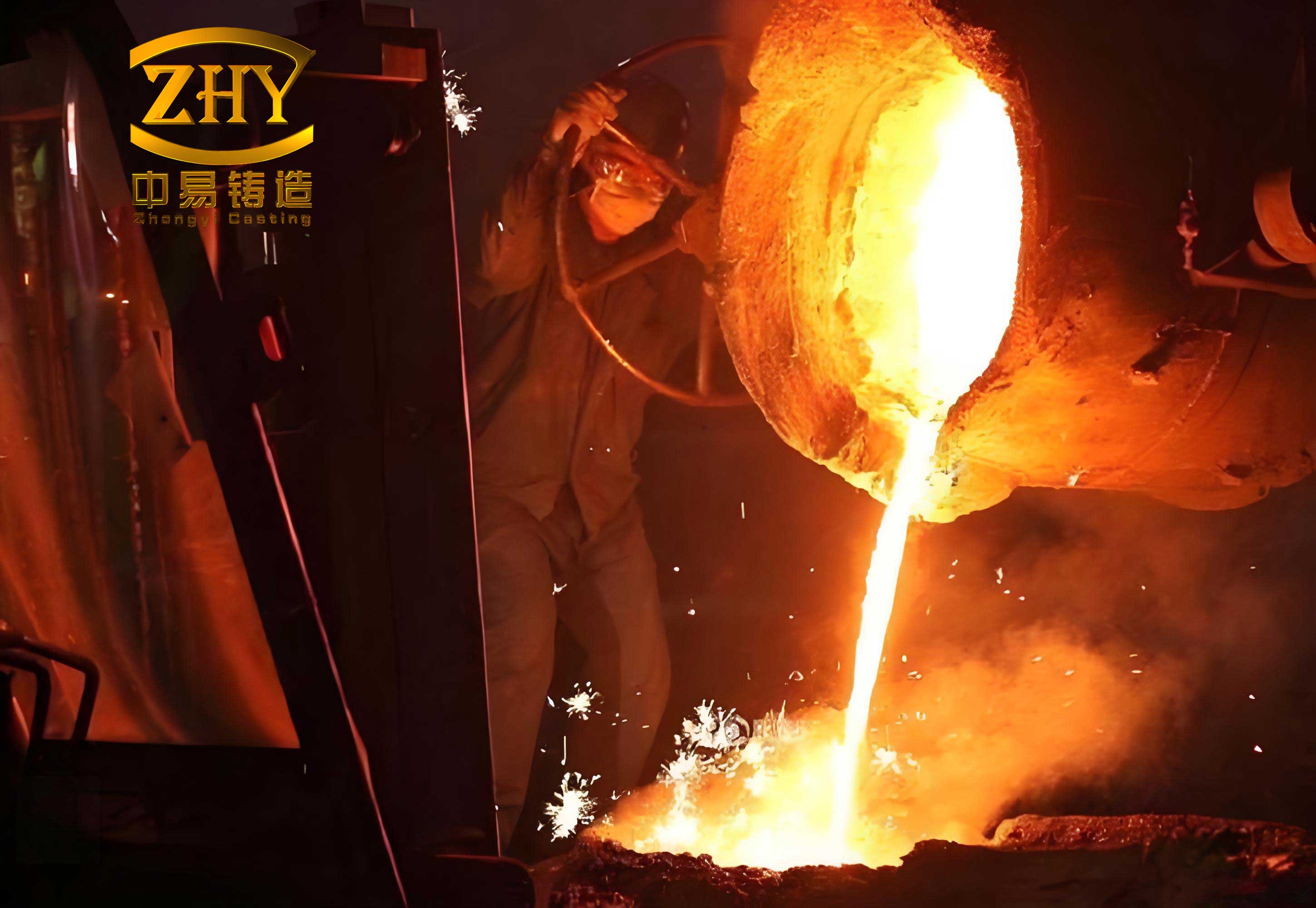
Critical to the lost foam casting process is the selection of material properties and process variables. The EPS foam pattern, with low density and specific thermal characteristics, decomposes upon contact with molten iron, creating a gap that influences heat transfer. We characterized the thermophysical parameters of HT250 gray iron and EPS foam, as summarized in Table 1. These parameters are essential for accurate simulation of the filling and solidification phases. The relationship between thermal conductivity, density, and latent heat governs the rate of foam degradation and metal cooling, which can be expressed through Fourier’s law of heat conduction: $$ q = -k \nabla T $$ where \( q \) is the heat flux, \( k \) is the thermal conductivity, and \( \nabla T \) is the temperature gradient. In the lost foam casting process, the interface heat transfer between the metal and foam is complex, involving pyrolysis reactions that release gaseous products.
| Material | Density ρ (kg/m³) | Specific Heat c (kJ/kg·K) | Latent Heat Q (kJ/kg) | Thermal Conductivity λ (W/m·K) | Solidus Temperature T_s (°C) | Liquidus Temperature T_l (°C) |
|---|---|---|---|---|---|---|
| HT250 | 6800-7300 | 0.56-0.93 | 256 | 34.27-54.87 | 1133 | 1222 |
| EPS Foam | 25 | 3.7 | 100 | 0.15 | 330 | 350 |
For the gating design, we employed a system with a sprue cross-section of 50 mm × 50 mm and a total height of 7300 mm, connected to a horizontal runner of 50 mm × 50 mm × 1150 mm, feeding 28 ingates each with a section of 28 mm × 10 mm. This configuration aims to distribute molten iron evenly and minimize velocity fluctuations. The mold was constructed using dry quartz sand (40-70 mesh) in a flask of 1500 mm × 1000 mm × 1300 mm, with a sand cushion of 200 mm at the bottom and 100-150 mm on the sides. A vacuum pressure of -0.05 MPa was applied to compact the sand and remove pyrolysis gases. The coating, based on quartz powder, was applied to a thickness of 1.5 mm initially, though we later adjusted it locally to 2 mm based on trial outcomes. The pouring temperature was set at 1540°C, with a sand temperature of 25°C and a pouring time of 80 seconds, derived from empirical formulas for filling rate in the lost foam casting process: $$ t_p = \frac{V_{cavity}}{A_{ingate} \cdot v} $$ where \( t_p \) is the pouring time, \( V_{cavity} \) is the cavity volume (0.7 m³), \( A_{ingate} \) is the total ingate area, and \( v \) is the flow velocity, typically controlled to avoid turbulence.
To simulate the lost foam casting process, we utilized ProCAST software, which incorporates finite element analysis for coupled thermal-fluid dynamics. The 3D model was meshed with 10 mm elements for the casting and gating system, and 50 mm elements for the sand mold, resulting in 963,619 nodes and 5,980,057 elements. Key simulation parameters included the definition of the lost foam casting method, gravity direction, material assignments, and boundary conditions. The heat transfer coefficient at the metal-foam interface was set to 0.0837 N/(s·mm·°C), denoted as FOAMTHC in ProCAST, to account for the pyrolysis zone. For the metal-sand interface, a coefficient of 500 W/(m²·K) was used, while the sand-environment interface was set to natural convection. The initial conditions aligned with the practical setup, enabling a realistic prediction of defect formation.
The filling simulation revealed the dynamic behavior of molten iron in the lost foam casting process. As shown in Figure 3 of the original study (not reproduced here due to restrictions), the metal entered the cavity at 1.097 s, filled the bottom by 11.357 s, and progressively ascended with occasional surface fluctuations at the top regions, especially near thin sections and lateral planes. By 80 s, the cavity was fully filled, but the simulation indicated potential issues such as air entrapment and cold shuts due to irregular flow. The solidification simulation, analyzed through temperature contours, highlighted that the V-shaped outer regions of the cylinder block cooled slowest, creating hot spots prone to shrinkage defects. The solidification time \( t_s \) can be estimated using Chvorinov’s rule: $$ t_s = B \left( \frac{V}{A} \right)^n $$ where \( B \) is a mold constant, \( V \) is the volume, \( A \) is the surface area, and \( n \) is an exponent typically around 2. For the engine block, the high volume-to-area ratio in thick sections prolonged solidification, leading to thermal segregation.
Defect prediction via ProCAST indicated shrinkage porosity concentrated in the V-shaped outer walls, with a calculated shrinkage volume of 139.958 cm³ and a shrinkage rate of 39.439%. This aligned with the final temperature field, where these regions remained hottest longest. To mitigate this in the lost foam casting process, we modified the design by adding six risers on the V-shaped upper sections and six chills on the outer sides, as illustrated in Figure 6 of the original work. The risers, made of HT250, provided feed metal to compensate for solidification shrinkage, while the chills, made of graphite with high thermal conductivity (2000 W/(m²·K) at the metal-chill interface), accelerated cooling to promote directional solidification. We also increased the pouring temperature to 1560°C to reduce premature freezing and improve fluidity. The modified simulation showed complete elimination of shrinkage defects, validating the efficacy of these changes in the lost foam casting process.
| Parameter | Initial Value | Optimized Value | Role in Process |
|---|---|---|---|
| Pouring Temperature | 1540°C | 1560°C | Enhances metal fluidity and reduces early solidification |
| Vacuum Pressure | -0.05 MPa | -0.05 MPa | Maintains sand compaction and gas extraction |
| Coating Thickness (local) | 1.5 mm | 2 mm | Prevents sand erosion and improves insulation |
| Riser Addition | None | 6 units | Provides feed metal for shrinkage compensation |
| Chill Addition | None | 6 units (graphite) | Accelerates cooling in hot spots |
Transitioning to production, we conducted trial casts using the optimized lost foam casting process. The first trial, however, revealed slag holes at the thin-wall junctions between the V-shaped inner sections and the rib beams, as seen in Figure 8 of the original paper. Analysis traced these defects to multiple factors: inadequate slag removal during iron melting, insufficient coating strength leading to erosion under metal flow, and excessive EPS foam density causing incomplete decomposition and slag formation. The foam degradation kinetics can be modeled by an Arrhenius-type equation: $$ \frac{dm}{dt} = -A e^{-E_a/(RT)} $$ where \( dm/dt \) is the mass loss rate, \( A \) is a pre-exponential factor, \( E_a \) is activation energy, \( R \) is the gas constant, and \( T \) is temperature. If foam density is too high, the decomposition rate lags, leaving residues that become entrapped as slag.
To resolve these issues in the lost foam casting process, we implemented corrective measures: enhanced slag removal through multiple skimming operations, increased local coating thickness to 2 mm with multiple layers to resist冲刷, and controlled EPS density to ensure complete gasification. Additionally, we added slag traps at the top and V-shaped inner areas to collect floating impurities. The second production run yielded sound castings with no leakage under pressure testing, confirming the robustness of the adjusted lost foam casting process. The final parameters—pouring temperature of 1560°C, vacuum of -0.05 MPa, and local coating thickness of 2 mm—proved effective for high-quality engine blocks.
Beyond this specific case, the lost foam casting process offers broader insights for industrial applications. The integration of simulation tools like ProCAST allows for predictive optimization, reducing trial-and-error costs. Key equations governing heat transfer and solidification in the lost foam casting process include the energy conservation equation: $$ \rho c_p \frac{\partial T}{\partial t} = \nabla \cdot (k \nabla T) + \dot{q}_{gen} $$ where \( \rho \) is density, \( c_p \) is specific heat, \( T \) is temperature, \( t \) is time, and \( \dot{q}_{gen} \) represents heat generation from foam pyrolysis. Coupling this with fluid flow equations enables accurate modeling of the complex interactions. Table 3 summarizes the simulation inputs and outputs for the lost foam casting process, highlighting the correlation between parameters and defect formation.
| Simulation Aspect | Input Value | Simulated Outcome | Impact on Defects |
|---|---|---|---|
| Mesh Size (casting) | 10 mm | High resolution of thermal gradients | Accurate shrinkage prediction |
| Interface HTC (metal-foam) | 0.0837 N/(s·mm·°C) | Realistic foam degradation rate | Affects filling stability and gas evolution |
| Pouring Time | 80 s | Complete filling achieved | Minimizes cold shuts but may cause turbulence |
| Solidification Time | ~3535 s | Slow cooling in thick sections | Increases shrinkage risk |
In conclusion, the lost foam casting process, when meticulously designed and simulated, can produce high-integrity castings like engine cylinder blocks. Our work demonstrates the importance of iterative refinement using tools like ProCAST to identify and rectify defects before physical production. The optimized parameters—1560°C pouring temperature, -0.05 MPa vacuum, and 2 mm local coating—along with strategic use of risers and chills, ensure a reliable lost foam casting process. Future advancements may focus on real-time monitoring and adaptive control to further enhance the efficiency and sustainability of the lost foam casting process. As manufacturing evolves, the lost foam casting process will continue to play a pivotal role in achieving near-net-shape components with reduced environmental footprint, solidifying its status as a key technology for the 21st century.
To generalize the findings, the lost foam casting process can be mathematically described through a set of governing equations that balance mass, momentum, and energy. For instance, the continuity equation for incompressible flow during filling is: $$ \nabla \cdot \mathbf{v} = 0 $$ and the Navier-Stokes equation: $$ \rho \left( \frac{\partial \mathbf{v}}{\partial t} + \mathbf{v} \cdot \nabla \mathbf{v} \right) = -\nabla p + \mu \nabla^2 \mathbf{v} + \rho \mathbf{g} $$ where \( \mathbf{v} \) is velocity, \( p \) is pressure, \( \mu \) is viscosity, and \( \mathbf{g} \) is gravity. In the lost foam casting process, these are coupled with a volume-of-fluid method to track the metal-foam interface. Additionally, the shrinkage volume \( V_{sh} \) can be estimated from the solidification contraction coefficient \( \beta \): $$ V_{sh} = \beta V_{casting} (T_l – T_s) \alpha $$ where \( \alpha \) is a geometric factor. By applying such models, the lost foam casting process becomes more predictable and controllable, enabling wider adoption for complex parts. Our experience underscores that success in the lost foam casting process hinges on a holistic approach combining simulation, material science, and practical adjustments, paving the way for innovation in foundry industries worldwide.