
The Expandable Polystyrene (EPS) foam pattern serves as the sacrificial core in the lost foam casting (LFC) process. Its characteristics, from the initial bead morphology to the final fused foam model, profoundly influence every stage of the process—including bead handling, mold filling, pattern assembly, coating, and ultimately, the surface finish and internal soundness of the resulting metal casting. A comprehensive understanding of EPS material properties is therefore not merely academic but a practical necessity for optimizing lost foam casting operations, controlling casting defects, and selecting suitable alloy systems. This article presents a detailed investigation into the characterization, thermal decomposition behavior, and mechanical properties of EPS materials used in lost foam casting, drawing upon analytical techniques to build a foundational knowledge base for process improvement.
1. Introduction to EPS and the Lost Foam Casting Context
Expandable Polystyrene (EPS) is a hydrocarbon polymer derived from the monomer styrene, with a typical elemental composition of approximately 92% carbon and 8% hydrogen. For use in lost foam casting, the polystyrene is synthesized into small, spherical beads impregnated with a low-boiling-point blowing agent, traditionally pentane. In its raw, unexpanded state, EPS beads have a high bulk density. The lost foam casting process necessitates a pre-expansion step where these raw beads are exposed to steam, causing the pentane to volatilize and the polystyrene to soften and expand, forming closed, non-interconnecting cellular structures. These pre-expanded beads are then used to fill a mold, where a second steam cycle fuses them together into a coherent, low-density foam pattern of the desired component geometry.
The performance of this foam pattern during lost foam casting is multifaceted. Its surface topography dictates the surface roughness transferred to the metal casting. Its thermal decomposition kinetics govern the gas evolution rate during metal pouring, which must be managed to prevent defects like porosity or folds. Its mechanical strength must be sufficient to withstand handling, coating, and sand compaction without distortion. Consequently, this study systematically examines: the morphological evolution of EPS beads from raw to pre-expanded states; the resultant surface roughness of foam patterns; the thermal degradation profile under atmospheric conditions; and the quasi-static mechanical response and fracture morphology of fused EPS models.
2. Morphological Characterization of EPS Beads
The shape, size, and size distribution of EPS beads significantly impact their flowability during pneumatic conveyance and mold filling, the packing density within the pattern mold, and the final surface quality of the foam pattern. To quantify these parameters, dynamic image analysis using a system like QICPIC (Quick Picture) is employed. This technique provides statistical data on particle size and shape descriptors such as sphericity, aspect ratio, and convexity for a large population of beads.
2.1 Particle Shape Analysis: Raw vs. Pre-expanded Beads
Representative micrographs and analysis data highlight distinct differences between raw and pre-expanded EPS beads. Raw beads generally exhibit good individual integrity, though with some variation in size and sphericity. In contrast, pre-expanded beads show more irregular shapes, including “defective” forms, concave “bay” shapes, and localized “crescent” shapes, resulting from the non-uniform stress and expansion during the steaming process.
Key shape parameters are defined as follows:
- Aspect Ratio: The ratio of the minimum to maximum Feret diameter of a particle’s projection. A value of 1 indicates a perfect circle.
- Sphericity: The ratio of the perimeter of a circle with the same area as the particle projection to the actual perimeter of the projection. A value of 1 indicates a perfect sphere.
- Convexity: The ratio of the actual particle area to the area of its convex hull. It measures surface roughness or indentation; a value of 1 indicates a perfectly convex shape.
The statistical summary of these parameters is best presented in a comparative table:
| Parameter | Raw EPS Beads (S10 / S50 / S90) | Pre-expanded EPS Beads (S10 / S50 / S90) |
|---|---|---|
| Aspect Ratio | 0.95 / 0.97 / 0.99 | 0.97 / 0.98 / 0.99 |
| Sphericity | 0.77 / 0.85 / 0.93 | 0.83 / 0.85 / 0.86 |
| Convexity | 0.95 / 0.97 / 0.98 | 0.98 / 0.99 / 0.99 |
| Particle Size (X10 / X50 / X90), μm | 402.79 / 467.18 / 522.43 | 1228.03 / 1554.61 / 1832.09 |
Analysis of the cumulative sphericity distribution curve, Q3(x), reveals further insight. For raw beads, the curve shows a steep initial slope plateauing near a sphericity of 0.87, indicating that a significant portion (about 18.45%) of beads have a sphericity greater than 0.87. For pre-expanded beads, the plateau occurs near 0.86, with only about 8.48% of beads exceeding this value. This suggests a slight overall decrease in sphericity during expansion. However, the sphericity distribution for pre-expanded beads is notably sharper and more concentrated around 0.83-0.86 compared to the broader distribution of raw beads. This higher consistency in sphericity among pre-expanded beads can be beneficial for improving flowability and mold filling uniformity in lost foam casting.
2.2 Particle Size Distribution Analysis
The transformation from raw to pre-expanded beads involves a substantial volume increase. The particle size data (X50) shows pre-expanded beads are approximately 3.3 times larger in diameter than raw beads, corresponding to a volume expansion factor of about 38. The size distribution curves are even more telling. The frequency distribution (q*3) curve for raw beads is tall and narrow, indicating a very uniform and tightly controlled initial size. The cumulative curve has a very steep initial slope. Conversely, the frequency distribution for pre-expanded beads is lower and broader (flatter peak). This wider distribution in the pre-expanded state can actually be advantageous for lost foam casting, as it allows smaller beads to fill interstitial voids between larger ones, potentially leading to a more densely packed and smoother-surface foam pattern.
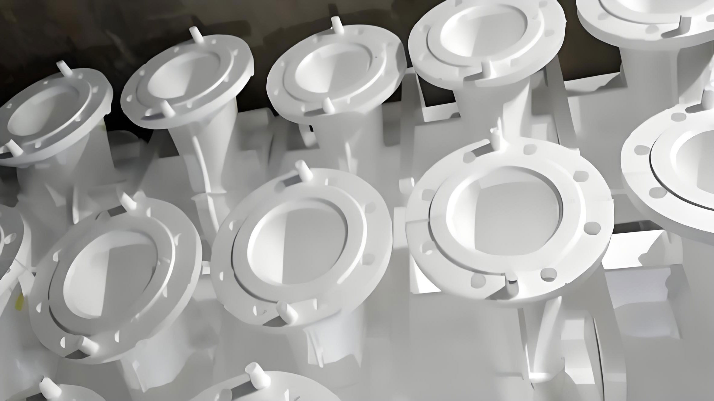
The pre-expansion process is critical in lost foam casting. Saturated dry steam at pressures of 120-160 kPa and temperatures of 120-150°C is used to heat the raw beads. The pentane blowing agent volatilizes, causing the softened polystyrene to expand. Subsequent conditioning (aging) allows air to diffuse into the cells, stabilizing the beads and improving their elasticity and flowability for the final pattern molding stage.
3. Surface Roughness Analysis of EPS Materials
The surface finish of the EPS pattern is directly replicated onto the metal casting in lost foam casting. Therefore, understanding and controlling pattern roughness is paramount. Non-contact 3D optical profilometry (e.g., white light interferometry) allows for precise measurement of surface topography at different stages.
Measurements are taken on individual raw beads, pre-expanded beads, and on the surface of a fused EPS pattern. The pattern surface analysis includes regions both with and without the imprint from steam venting nozzles used in the pattern molding tool. These nozzle marks are a common feature and can significantly affect local roughness.
The quantitative results are summarized below:
| Material / Surface | Average Surface Roughness (Sa), μm |
|---|---|
| Raw EPS Bead | 1.28 |
| Pre-expanded EPS Bead | 6.09 |
| EPS Pattern (no nozzle imprint) | 6.94 |
| EPS Pattern (with nozzle imprint) | 16.09 |
The data reveals a clear trend: the pre-expansion process increases surface roughness by a factor of approximately 5 compared to the raw bead. The surface of a fused pattern in an unaffected area is slightly rougher still than a single pre-expanded bead, likely due to the incomplete fusion and the remnants of bead boundaries. Most critically, the presence of a nozzle imprint drastically increases local roughness by a factor of about 2.3 compared to the unimprinted area. This highlights a key practical consideration for lost foam casting tooling design: a balance must be struck between sufficient venting for steam during pattern molding (requiring nozzles) and minimizing their detrimental impact on the pattern’s, and hence the casting’s, surface finish. Optimizing nozzle distribution, size, and design to achieve adequate steaming with minimal surface marking is essential for high-quality lost foam casting production.
4. Thermal Decomposition Behavior of EPS Materials
During the lost foam casting process, the EPS pattern is rapidly decomposed by the incoming molten metal. The rate and nature of this decomposition—whether it melts, vaporizes, or burns—governs the volume and pressure of gases produced, which must be evacuated through the coating and sand mold to prevent casting defects. Thermogravimetric Analysis (TGA) and Differential Thermal Analysis (DTA) under an air atmosphere provide crucial data on the weight loss and thermal events associated with heating EPS.
Comparative TGA/DTA curves for raw and pre-expanded EPS beads reveal fundamentally different profiles:
Raw EPS Beads: The TGA curve shows two distinct weight loss stages. The first, a physical weight loss of about 3.56%, begins near 107°C and is associated with the volatilization of the pentane blowing agent. This is confirmed by an endothermic dip in the DTA curve at 124.7°C. The second, a chemical weight loss of about 95.48%, begins around 243°C, marking the onset of polymer chain scission and decomposition. This stage features a rapid weight loss rate with an exothermic peak in the DTA at 319.4°C, indicating combustion. A second, broader exothermic peak occurs at 516.1°C. At 600°C, the residual ash (mainly carbonaceous) is about 0.84%.
Pre-expanded EPS Beads: The TGA curve shows essentially one major chemical weight loss stage. The physical weight loss stage is negligible because most of the pentane has already been expended during pre-expansion. Chemical decomposition begins around 255°C, followed by a very rapid, concentrated weight loss (94.93%) between approximately 325°C and 425°C. This is accompanied by a sharp exothermic DTA peak at 324.9°C. A smaller, later exotherm is seen near 497.6°C. The residual at 600°C is higher, at about 2.52%.
The implications for lost foam casting are significant:
- Pre-expansion Guidance: The onset of pentane loss near 107°C for raw beads sets a practical upper temperature limit for the pre-expansion and subsequent bead storage/handling to preserve the blowing agent for the final pattern molding stage.
- Decomposition Kinetics: The pre-expanded bead’s decomposition is characterized by a narrow, high-rate weight loss interval. This “burst” decomposition generates a large gas volume in a short time during metal pouring. This underscores the critical importance of applying a vacuum to the sand mold in lost foam casting to instantly evacuate these gases, preventing them from being entrapped in the solidifying metal.
- Alloy Selection Guidance: Since chemical decomposition of the pre-expanded pattern is essentially complete by 425°C, the pouring temperature of the alloy used in lost foam casting should significantly exceed this threshold—typically by at least 150°C—to ensure the pattern is consumed quickly and cleanly ahead of the advancing metal front. This makes lost foam casting particularly suitable for ferrous alloys and higher-melting-point non-ferrous alloys.
- Carbon Residue: The higher carbon residue from pre-expanded beads suggests that for alloys sensitive to carbon pickup (e.g., some stainless steels or ductile iron), the pattern chemistry and process conditions must be carefully controlled to minimize this potential source of casting contamination.
The thermal decomposition can be modeled in stages corresponding to foam density. For a pre-expanded bead density of ~0.019 g/cm³:
- Softening Region: ~75 – 164°C
- Melting Region: ~164 – 316°C
- Gasification Region: ~316 – 576°C
- Combustion Region: >576°C
The rapid exothermic reaction in the gasification region is the primary driver of pattern removal in the lost foam casting process.
5. Mechanical Properties and Fracture Morphology of EPS Models
The EPS pattern must possess adequate mechanical integrity for handling before casting. Studying its stress-strain behavior and fracture mode provides insight into its durability. A uniaxial tensile test was performed on a dog-bone specimen machined from a fused EPS pattern block. The test was monitored using a 3D Digital Image Correlation (DIC) system to capture full-field strain data.
5.1 Tensile Behavior and Properties
The force-displacement data and DIC analysis reveal the deformation mechanics of the EPS model material under quasi-static loading at room temperature. The behavior can be segmented into three regimes:
- Linear Elastic Region (0-200s): The material exhibits a near-linear relationship between stress and strain, with minimal permanent deformation.
- Uniform Plastic Deformation & Strengthening Region (200-560s): Beyond the yield point, the material deforms plastically. The DIC-derived strain maps show uniform elongation across the gauge length, with some strain hardening observed.
- Localized Necking and Fracture Region (560-761s): Deformation localizes into a neck, leading to final fracture. The DIC data shows a sharp concentration of axial strain (EZZ) at the failure location.
From the test, key mechanical properties for the EPS model material are derived:
- Maximum Force (Fb): 38 N
- Original Cross-sectional Area (S0): Based on an initial average radius of 5.42 mm, S0 ≈ 92.2 mm².
- Final Cross-sectional Area at Fracture (S1): Based on an average radius at fracture of 5.08 mm, S1 ≈ 81.1 mm².
The tensile strength (Rm) and ductility measures are calculated as follows:
$$ R_m = \frac{F_b}{S_0} = \frac{38}{92.2} \approx 0.41 \text{ N/mm}^2 = 0.41 \text{ MPa} $$
$$ \text{Elongation after Fracture (A)} = \frac{L_1 – L_0}{L_0} \times 100\% \approx 12.9\% $$
$$ \text{Reduction of Area (Z)} = \frac{S_0 – S_1}{S_0} \times 100\% = \frac{92.2 – 81.1}{92.2} \times 100\% \approx 11.0\% $$
The significant plastic elongation (12.9%) and the reduction in area (11.0%) confirm that the fused EPS model fails in a ductile manner. The low tensile strength (0.41 MPa) is characteristic of low-density foam structures but is sufficient for careful handling in the lost foam casting process chain.
5.2 Fracture Surface and Cellular Structure
Examination of the fracture surface via scanning electron microscopy (SEM) reveals the internal architecture of the EPS material. The structure is a classic closed-cell foam morphology. The view shows a honeycomb-like network of polygonal cells (vesicles) separated by thin walls. Key observations include:
- The cells are predominantly closed, with clear boundaries between them.
- Cell walls often have a wrinkled texture.
- Some cell walls have coalesced, forming larger, combined cells, while in other areas, incomplete fusion leaves gaps between adjacent pre-expanded bead domains.
- The average cell diameter is approximately 35 µm.
Given that the average pre-expanded bead size (X50) is about 1550 µm, one can estimate the number of cells per bead:
$$ \text{Volume of an average bead} \approx \frac{4}{3}\pi (775 \mu m)^3 \approx 1.95 \times 10^9 \mu m^3 $$
$$ \text{Volume of an average cell} \approx \frac{4}{3}\pi (17.5 \mu m)^3 \approx 2.24 \times 10^4 \mu m^3 $$
$$ \text{Estimated cells per bead} \approx \frac{1.95 \times 10^9}{2.24 \times 10^4} \approx 87,000 $$
This immense number of tiny, gas-filled cells is responsible for the material’s low density, low thermal conductivity, and good energy absorption—properties that are indirectly beneficial in lost foam casting by providing thermal insulation between the molten metal and the sand mold.
6. Conclusion and Integration for Lost Foam Casting Optimization
This comprehensive characterization of EPS materials provides actionable insights for advancing lost foam casting technology:
1. Morphology & Surface Control: The pre-expansion process transforms uniform, smooth raw beads into larger, slightly less spherical but more consistently shaped pre-expanded beads with a broadened size distribution and higher surface roughness. This distribution can enhance pattern packing density. The dominant factor affecting final pattern roughness is not the bead texture itself, but the artifact left by molding tool vents. Tooling design must prioritize minimizing these marks to achieve superior casting surface finish in lost foam casting.
2. Thermal Process Windows: The thermal analysis defines critical temperatures:
- <107°C: Safe zone for bead handling/storage to retain pentane.
- ~255-425°C: Critical decomposition window for pre-expanded patterns. The rapid, concentrated nature of gas evolution mandates the use of mold vacuum in lost foam casting for defect prevention.
- >575°C: Minimum recommended pouring temperature for most alloys to ensure complete pattern removal ahead of the metal front.
3. Mechanical Performance: The fused EPS pattern exhibits ductile failure with low strength but sufficient plasticity for normal handling. Its mechanical behavior is a direct consequence of its intricate closed-cell foam microstructure, which consists of tens of thousands of cells per pre-expanded bead.
In summary, the journey from a raw EPS bead to a functional sacrificial pattern in lost foam casting involves deliberate changes in morphology, surface state, and thermal readiness. By scientifically characterizing these properties—the bead shape and size distribution, the pattern roughness, the precise thermal degradation profile, and the mechanical resilience—foundries can make informed decisions to optimize pre-expansion parameters, tooling design, vacuum levels, and alloy selection. This systematic approach enables better control over the lost foam casting process, leading to castings with improved surface quality, dimensional accuracy, and internal soundness, while also addressing environmental concerns related to gas evolution. The data and relationships established here serve as a foundation for modeling, simulation, and continued refinement of this versatile casting technique.