
The production of cylinder heads for diesel engines using lost foam casting presents a unique set of challenges due to the part’s inherent geometric complexity. These components feature intricate internal networks including intake and exhaust ports, cooling water jackets, injector bores, and numerous bolt holes, all within walls that can be as thin as 5mm. Successfully replicating this complexity in a cast component requires exceptional dimensional accuracy, pressure tightness, and mechanical properties. The entire process hinges on the quality of the expendable foam pattern, or “white pattern.” Any imperfection in the foam pattern is directly transferred to the final metal casting. Therefore, rigorous quality control throughout the pattern-making process is not merely beneficial—it is an absolute prerequisite for producing sound, functional castings. This discussion will delve into the critical control points for white pattern quality, focusing on mold design, bead conditioning, pattern formation, coating application, and drying, providing a comprehensive framework for excellence in lost foam casting of high-integrity components.
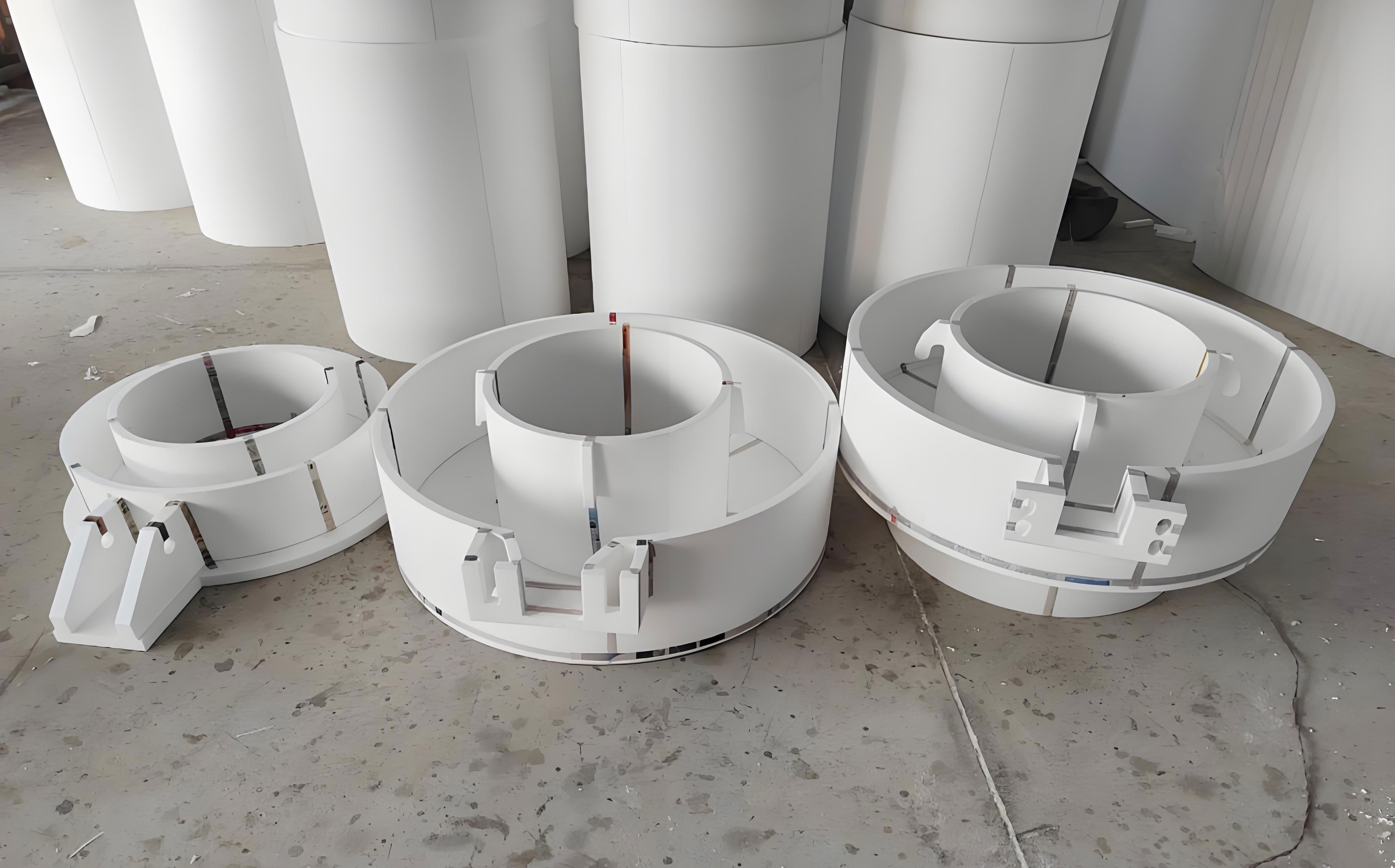
Given the undercuts and complex internal passages, the foam pattern for a cylinder head is typically manufactured in multiple segments—often four—which are subsequently assembled with adhesive. This segmentation strategy is fundamental to the lost foam casting process for such parts. The design of the parting lines is of paramount importance, especially concerning the intake and exhaust ports. These ports define critical engine performance parameters like flow coefficient and swirl ratio. The primary goal is to consolidate the core geometry of these ports within the fewest segments possible, ideally minimizing the number of glue lines intersecting the port walls. A single, well-controlled glue line is vastly preferable to multiple, misaligned ones which can create flow-disrupting steps in the final casting. Consequently, a significant portion of the port’s shape should be designed into the central pattern segments.
Precision Mold Design and Manufacturing
The journey to a perfect foam pattern begins with the mold tooling. The mold for lost foam casting is an aluminum tool that defines the shape of each foam segment. Its design and construction directly influence pattern density, surface finish, dimensional stability, and overall repeatability.
Material Selection and Construction: To withstand the cyclic thermal stresses of steam heating and water cooling, mold materials must exhibit excellent thermal conductivity, strength, and resistance to wear and corrosion. The preferred material for the main mold body, cores, frames, and steam chambers is forged 6061-T6 aluminum. This alloy, after solution heat treatment and stress-relieving, provides the necessary combination of properties. Mold plates are also manufactured from hard aluminum alloys. Critical components like cooling systems and locating pins are made from stainless steel or copper to prevent corrosion and ensure longevity.
Geometric and Thermal Design: Uniform wall thickness is crucial for consistent heating and cooling. The mold body walls are typically controlled within 12-15mm, providing sufficient strength while allowing rapid heat transfer. The external steam frame is thicker (18-20mm) and reinforced with ribs for structural integrity. An efficient, balanced cooling system utilizing high-efficiency water sprayers is essential to quickly solidify the fused foam beads and control cycle time. The design must ensure every section of the mold cavity cools at a similar rate to prevent differential shrinkage and distortion in the foam pattern.
Venting System (Air Slots): Perhaps one of the most critical aspects is the design and implementation of the venting system, consisting of thousands of precision air slots. These micro-perforations allow steam to penetrate the mold cavity and expand the raw beads, and later allow vacuum and water to cool the mold. Their distribution must be meticulously calculated—denser in thick sections and corners to ensure complete bead fusion, and sparser in thin walls to prevent over-packing or bead collapse. The surface finish of these slots is vital; they must be deburred and polished to prevent leaving visible impressions on the foam pattern surface, which would then translate to undesirable markings on the cast cylinder head after shot blasting.
Assembly and Gluing Tools: Beyond the primary molding tools, the fixtures used for assembling and gluing the pattern segments are equally important. The gluing fixtures, or jigs, must hold the individual foam segments in perfect alignment during adhesive curing. The mating surfaces of these jigs are often made from cast iron (like HT250, stress-relieved) or aluminum. Their precision ensures the glue line is minimal, flush, and does not create any protruding flash that would affect the aerodynamic properties of the ports.
| Component | Material | Key Specification/Requirement | Purpose |
|---|---|---|---|
| Mold Body, Cores, Frame | Forged 6061-T6 Aluminum (Heat Treated) | Wall Thickness: 12-15mm; Uniform Cooling Channels | Thermal stability, wear resistance, dimensional accuracy |
| Mold Plates | Hard Aluminum Alloy | High Surface Finish, Flatness | Defines pattern surface quality |
| Air Slots (Vents) | Stainless Steel Inserts | Precision diameter, polished surface, optimized distribution | Uniform steam penetration, no pattern surface marking |
| Cooling System Tubes/Sprays | Copper / Stainless Steel | Efficient, balanced flow design | Rapid and uniform mold cooling |
| Locating Pins & Bushings | Stainless Steel | High precision, hardened | Accurate mold closure and segment alignment |
| Gluing Fixture (Impression) | HT250 Cast Iron / Aluminum | Stress-relieved, precision-machined mating surfaces | Ensures flush, minimal glue lines on assembled pattern |
The Science of Bead Conditioning and Pre-Expansion
The raw material for lost foam casting is expandable polystyrene (EPS) or similar copolymer beads containing a blowing agent. The first transformation is pre-expansion, where the beads are exposed to steam, causing them to expand to a low density, typically in the range of 16-24 g/L for cylinder head applications. However, the process does not end there. Freshly pre-expanded beads are unstable, containing residual steam and pentane, and are prone to shrinkage. They must undergo a conditioning or “aging” period.
During this aging period, air diffuses into the beads while the blowing agent and moisture diffuse out, stabilizing the internal pressure. The goal is to achieve a state of equilibrium where the beads are dry, free-flowing, and have a consistent, predictable expansion potential during the final molding stage. The conditioning environment is therefore a critical process parameter in lost foam casting.
Optimal Conditioning Environment:
$$ \text{Conditioning Quality} \propto f(T_{air}, H_{rel}, t, A_{flow}) $$
Where:
$T_{air}$ is the air temperature (optimal range: 25-35°C),
$H_{rel}$ is the relative humidity (must be < 30%),
$t$ is the conditioning time (typically 4-24 hours depending on bead size and density),
$A_{flow}$ is the airflow over the beads.
Low humidity is essential to draw moisture from the beads. The conditioning silo or bin should be constructed from anti-static materials to prevent beads from clinging to walls. Its volume should be manageable (around 1 m³) to ensure uniform environmental exposure, and the mesh of the silo should allow for good air circulation while retaining the beads. Operator knowledge is key; they must understand how to assess bead readiness, often by checking flowability and compressibility by hand.
Forming the Pattern Segment: Process Control and Defect Prevention
In the pattern molding machine, the conditioned beads are blown into the closed, pre-heated aluminum mold. Steam is then injected through the air slots, causing the beads to soften, expand further, and fuse together at their boundaries, forming a solid, seamless foam replica of the mold cavity. After fusion, the mold is cooled with water sprays to set the shape before ejection.
Critical Quality Parameters for Foam Patterns:
1. Uniform Density: Every segment, and every region within a segment, must have identical density. This is controlled by uniform bead filling (using multiple fill guns if necessary), consistent steam pressure and timing, and balanced mold heating/cooling. Density variation leads to differential degradation during pouring and uneven metal fill.
2. Complete and Uniform Fusion: Beads must be fully fused without “under-cooked” (loose, sandy texture) or “over-cooked” (shrunken, caramelized) areas. This is a function of the steam cycle (pressure, time) and the mold’s thermal profile.
3. Dimensional Accuracy: The pattern must match the mold dimensions within tight tolerances. This is governed by precise control of the molding cycle times—too short a cycle leads to spring-back and growth; too long leads to excessive shrinkage. Consistency is vital to ensure all four segments fit together perfectly during gluing, especially at critical interfaces like the port dividers.
| Defect | Visual / Tactile Identification | Root Causes | Corrective Actions |
|---|---|---|---|
| Localized Distortion / Warpage | Pattern segment is bent or twisted; does not sit flat on gluing fixture. | Non-uniform ejection (suction cup misalignment); localized overheating in mold; uneven cooling. | Adjust suction cup positions for balanced force; perform several machine dry cycles to normalize mold temperature; check cooling line balance. |
| Over-fused / “Burnt” Pattern | Yellowish or brown discoloration; shrunken, dense, brittle texture; glossy surface. | Excessive steam pressure or dwell time; insufficient cooling time; mold temperature too high. | Reduce steam pressure and/or fusion time; increase water cooling cycle duration; verify mold heater calibration. |
| Under-fused / “Sandy” Pattern | Beads are not fully fused; pattern feels crumbly and lacks strength; visible bead boundaries. | Insufficient steam pressure or dwell time; clogged air slots or fill guns; low mold temperature. | Increase steam pressure and/or fusion time; clean air slots and fill guns; ensure proper mold pre-heat. |
| Poor Surface Finish (Bead Imprint) | Distinct imprint of individual beads on pattern surface; rough texture. | Beads too large for wall thickness; insufficient steam penetration; air slots too large or poorly finished. | Use smaller bead grade for thin walls; optimize steam cycle; inspect and polish air slots. |
| Incomplete Filling | Missing geometry, especially in thin sections or deep draws. | Low bead fill pressure; blocked fill gun for that cavity section; vent blockage in that area. | Increase fill pressure; clear blocked fill lines and vents; revise fill gun placement. |
The mathematical relationship for achieving uniform fusion can be conceptualized by balancing the energy input from steam with the heat absorption of the mold and beads:
$$ Q_{steam} = m_{beads} \cdot c_{p,beads} \cdot \Delta T + m_{mold} \cdot c_{p,Al} \cdot \Delta T_{mold} + Q_{loss} $$
Where a consistent $Q_{steam}$ (controlled by P, t) and a stable initial $T_{mold}$ are necessary for repeatable results across every cycle and every cavity in lost foam casting.
The Art and Science of Coating Application (Dip Coating)
Once the multi-segment pattern is assembled into a complete “cluster” (often including the gating system), it is dipped into a refractory slurry. This coating serves multiple vital functions in lost foam casting: it provides a barrier between the metal and the sand, it confers strength to withstand sand compaction, it allows gaseous decomposition products from the foam to escape, and it ensures a good surface finish on the final casting.
Challenge of Complex Geometry: The internal passages of a cylinder head—intersecting ports, narrow water jacket gaps (sometimes < 3mm), and blind pockets—create severe challenges for coating. The chosen dipping orientation must allow the slurry to flow into and, crucially, drain out of all internal cavities to avoid excessive buildup. Puddles of thick, undrained coating will not dry properly, leading to retained moisture that causes gas defects, blows, or inclusions during the pour. A systematic approach involves defining a specific dipping angle for each pattern cluster design that minimizes “dead zones.”
Quantitative Process Control: While monitoring the slurry viscosity (often by Baume gravity) is standard practice, it is not sufficient for a high-reliability process like cylinder head lost foam casting. A far more robust method is the direct measurement and control of cluster weight. The process typically involves two dipping cycles:
1. First Dip: The dry, uncoated cluster is weighed. After dipping and allowing excess to drain, it is weighed again (“wet weight post-dip 1”). After the first drying stage, it is weighed a third time (“dry weight post-dip 1”).
2. Second Dip: The same cluster undergoes a second dip. The wet and dry weights are measured again.
This data provides direct, quantitative insight into the actual coating mass applied and retained, which correlates directly to coating thickness. This method eliminates variability from subjective assessments of “drip time” or “coverage.”
| Pattern Type | 1st Dip Baume (°) | 1st Dip Wet Weight (kg) | 1st Dip Dry Weight (kg) | 2nd Dip Baume (°) | 2nd Dip Wet Weight (kg) | Final Cluster Dry Weight (kg) |
|---|---|---|---|---|---|---|
| Model 4102 | 55 | 2.2 – 2.5 | 1.0 – 1.2 | 55 | 3.7 – 4.0 | 2.1 – 2.3 |
| Model 4C6 / 490 | 56 | 1.7 – 2.0 | 0.6 – 1.0 | 56 | 3.0 – 3.2 | 1.5 – 1.8 |
| Model 4B2 / 4B1 | 56 | 1.5 – 1.7 | 0.6 – 0.9 | 56 | 2.5 – 2.9 | 1.5 – 1.7 |
The target dry coating weight ($W_{coat}$) can be related to the desired average coating thickness ($t_{coat}$) and the pattern’s surface area ($A_{surf}$) and the coating’s dry density ($\rho_{coat}$), albeit in a complex geometry:
$$ W_{coat} \approx \int_{A_{surf}} \rho_{coat} \cdot t_{coat}(x,y,z) \, dA $$
The weight control method effectively integrates this complex function, ensuring the total $W_{coat}$ is within specification.
Additional Coating Steps: Areas subject to high metal turbulence, such as the base of the downsprue or sharp corners on the gating system, often receive an extra manual brush coat to reinforce the barrier against erosion. A critical final inspection involves checking all glue lines and joint areas for any coating cracks or gaps that must be repaired.
Precision Drying: Removing Moisture Without Distortion
The final, and often most time-consuming, step in pattern preparation is the thorough drying of the applied refractory coating. Residual moisture in the coating is a primary source of hydrogen gas defects and porosity in lost foam casting. The irregular shape of a cylinder head cluster, with its internal cavities and varying coating thicknesses, makes uniform drying a significant challenge.
Drying System Requirements: The dryer must provide not only heat but also excellent air circulation and, most importantly, moisture removal. Forced-air convection ovens with dehumidification capabilities or dedicated low-humidity drying rooms are essential. Temperature uniformity across the drying chamber is critical; variations can lead to uneven drying rates, causing residual damp spots or, conversely, thermal distortion of the foam pattern.
Staged Drying Protocol: A single high-temperature bake is detrimental. The process must be gradual:
Stage 1 (First Dip Drying): Gentle drying at lower temperatures (approximately 45°C) to remove the bulk of the water without causing rapid steam generation within the coating layer, which could cause blistering or cracking.
Stage 2 (Second Dip & Final Drying): After the second dip, the temperature can be raised, typically into the 50-55°C range. The final drying of the finished cluster aims to reduce the internal moisture content to an absolute minimum. This often requires an extended period of 5 to 7 days at a controlled temperature of 55-60°C, with the relative humidity inside the dryer maintained below 10%.
Process Monitoring and Control: Modern dryers are equipped with multiple zone thermocouples and humidity sensors. Data logging is crucial to verify process consistency. Parameters such as average temperature, max/min temperature spread, humidity, and drying time must be tracked for each batch. To counteract potential hot or cold spots in the dryer, it is a good practice to periodically rotate the positions of the pattern carrier trolleys during the extended drying cycle.
The drying process can be modeled as a diffusion problem, where the rate of moisture removal is governed by Fick’s second law, with boundary conditions set by the oven’s temperature ($T_{oven}$) and humidity ($H_{oven}$):
$$ \frac{\partial C}{\partial t} = D(T_{coat}) \cdot \nabla^2 C $$
$$ \text{Boundary: } -D \frac{\partial C}{\partial n} = h_m (C_{surface} – C_{eq}(T_{oven}, H_{oven})) $$
Where $C$ is moisture concentration, $D$ is the moisture diffusivity in the coating (temperature-dependent), and $h_m$ is the mass transfer coefficient. The goal is to drive $C$ throughout the entire coating volume to near zero.
Integrated Quality System for Lost Foam Casting
Producing a high-quality cylinder head via lost foam casting is not the result of excelling at one step, but of stringent control across an interconnected chain. The system can be summarized as follows:
1. Pattern Mold Foundation: A precision mold with rational parting lines, uniform venting, and thermal balance is the non-negotiable starting point.
2. Material Consistency: Strict control over bead pre-expansion and conditioning ensures a stable, predictable raw material.
3. Molding Process Stability: Repeatable cycles with controlled steam, pressure, time, and cooling yield pattern segments with uniform density, fusion, and dimensions.
4. Quantified Coating Application: Using weight-based control alongside viscosity checks guarantees a consistent, effective refractory barrier tailored to the complex geometry.
5. Definitive Drying: A monitored, staged drying process in a capable dryer eliminates moisture, the final major source of casting defects.
Each of these pillars supports the other. A perfect mold is wasted on poorly conditioned beads. A perfectly formed pattern can be ruined by a non-uniform coating. And a perfectly coated cluster will produce scrap if it retains moisture. Therefore, the core philosophy in lost foam casting, especially for critical components like cylinder heads, must be one of systemic process control, where each variable is measured, managed, and optimized in the context of the entire sequence. This holistic approach transforms the challenges of complexity into the reliable production of high-integrity castings.