
In our foundry, we continuously strive to enhance the quality and reliability of complex cast components. One of the most demanding projects we have undertaken involves the production of large, heavy-duty coupler heads for railway vehicles. These components are subjected to extreme and multifaceted loading conditions—including significant impact, tensile, compressive, and torsional forces during service. The coupler’s structural integrity is paramount; fatigue failure, often initiating from stress concentrations in critical zones like the connection between the hook head and the hook tongue, is a primary concern. To manufacture these geometrically intricate and heavily loaded parts, we rely on the precision investment casting process. This near-net-shape technique is ideal for achieving the required dimensional accuracy and surface finish for such complex geometries. However, casting a component of this size and sectional variance presents significant challenges in defect control, particularly regarding shrinkage porosity and hot tearing, which directly impact production yield and component safety.
The inherent advantages of precision investment casting are sometimes counterbalanced by the difficulties in ensuring soundness throughout thick sections and complex junctions. The coupler head, with a bounding box of approximately 594 mm × 370 mm × 350 mm and a mass of around 70 kg, features dramatic variations in wall thickness, from roughly 12 mm at the thinnest sections to over 43 mm at the thickest. This non-uniform geometry disrupts ideal solidification patterns, leading to isolated hot spots. In our initial trials using a conventional gating approach, we consistently observed subsurface cracks and shrinkage cavities in the critical load-bearing area linking the hook head and the hook tongue. These defects, identified through fluorescent magnetic particle inspection, necessitated costly weld repairs or led to outright scrap, highlighting a pressing need for process optimization.
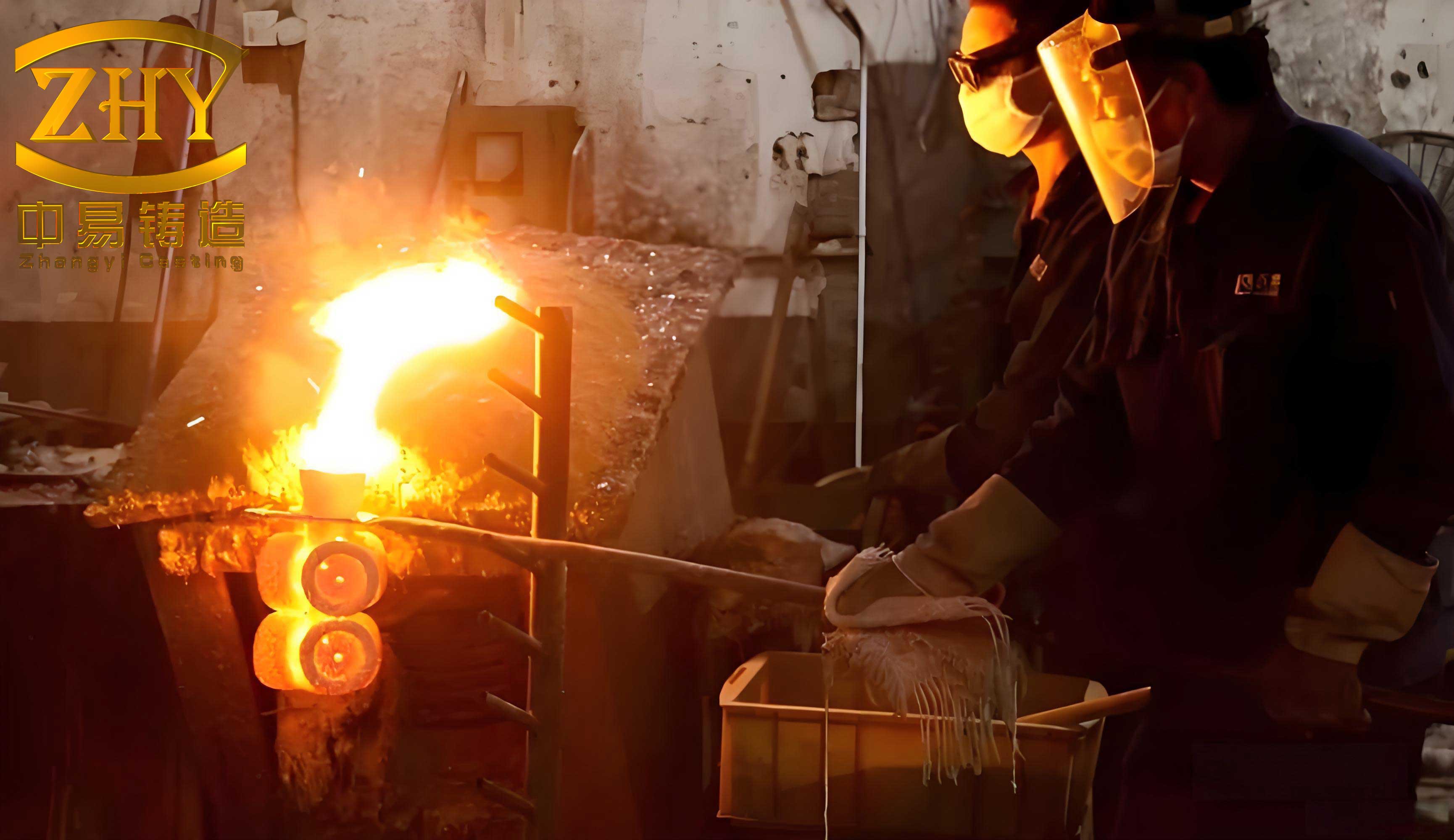
To address these challenges without resorting to costly and time-consuming physical trial-and-error, we turned to advanced numerical simulation. Computer-aided engineering (CAE) has become an indispensable tool in modern foundries, allowing for the virtual prototyping of the entire casting process. We utilized ProCAST software to simulate the coupled filling and solidification processes, enabling us to analyze temperature fields, fluid flow, stress development, and predict defect formation. The goal was to design a gating and feeding system that promotes directional solidification, minimizes thermal stresses, and effectively feeds shrinkage, thereby eliminating defects in critical areas. The material specified for this component is a high-strength low-alloy cast steel, ZG25MnCrNiMo, whose thermophysical properties are crucial for accurate simulation. Key properties like thermal conductivity ($$k$$) and density ($$\rho$$) vary non-linearly with temperature ($$T$$), and their accurate representation is essential. We can express the dependence of enthalpy ($$H$$) on temperature as an integral of the specific heat capacity ($$C_p$$):
$$ H(T) = \int_{T_{ref}}^{T} \rho(\tau) C_p(\tau) d\tau $$
where $$T_{ref}$$ is a reference temperature. The simulation input for these properties was derived from the actual alloy composition, as summarized in Table 1.
| Element | C | Si | Mn | Cr | Ni | Mo | P | S | Fe |
|---|---|---|---|---|---|---|---|---|---|
| Content | 0.26 | 0.45 | 1.40 | 0.55 | 0.45 | 0.25 | ≤0.035 | ≤0.035 | Bal. |
We conceived and virtually tested two distinct gating system philosophies, designated Scheme A and Scheme B. The primary boundary conditions and process parameters for the simulations are consolidated in Table 2. Scheme A was designed with a focus on material yield and simplicity. It featured a single, horizontal side-gate with a top riser placed over a flange section. The intent was to minimize the volume of the gating system for economic efficiency. Scheme B was designed with a focus on robust feeding. It employed a vertical, symmetrical two-gate arrangement, with significantly larger runner bars strategically attached to the thick shoulder sections of the hook head. A top riser was also incorporated. The increased thermal mass of the gating system in Scheme B was intended to act as a effective feeder, promoting a more favorable thermal gradient.
| Parameter | Scheme A | Scheme B |
|---|---|---|
| Pouring Temperature | 1550 °C | 1580 °C |
| Shell Preheat Temperature | 400 °C | 400 °C |
| Ambient Temperature | 25 °C | 25 °C |
| Filling Time | 15 s | 30 s |
| Interface Heat Transfer Coefficient (Metal/Shell) | 500 W·m⁻²·K⁻¹ | |
| Shell/Air Heat Transfer Coefficient | 10 W·m⁻²·K⁻¹ | |
The simulation of the filling phase provided immediate insights. For Scheme A, the initial metal entry was turbulent, with localized velocities reaching 0.71 m/s, indicating a potential for mold erosion and gas entrapment. While the mold filled completely, the flow dynamics were less than ideal. In contrast, Scheme B exhibited a remarkably calm and orderly fill. The symmetrical gates balanced the metal entry, and the maximum flow velocity was reduced to 0.48 m/s. This smoother fill is critical in precision investment casting to avoid surface defects and oxide inclusions. The governing equations for fluid flow during this phase include the Navier-Stokes equations for incompressible flow with a free surface:
$$ \nabla \cdot \vec{v} = 0 $$
$$ \frac{\partial \vec{v}}{\partial t} + (\vec{v} \cdot \nabla) \vec{v} = -\frac{1}{\rho} \nabla p + \nu \nabla^2 \vec{v} + \vec{g} $$
where $$\vec{v}$$ is the velocity vector, $$p$$ is pressure, $$\nu$$ is the kinematic viscosity, and $$\vec{g}$$ is gravity. The lower velocities in Scheme B resulted in a lower Reynolds number ($$Re = \frac{\rho v L}{\mu}$$), indicating more laminar flow characteristics.
The most critical analysis lay in the solidification simulation. The results starkly differentiated the two schemes. Scheme A exhibited a highly undesirable solidification pattern. Thin walls and sections near the gate solidified rapidly, isolating the larger thermal mass at the critical hook head/hook tongue junction. This created a significant isolated liquid “hot spot,” as visualized by a prolonged liquid fraction in that region. The solidification time ($$t_s$$) for a section can be approximated by Chvorinov’s rule:
$$ t_s = B \left( \frac{V}{A} \right)^n $$
where $$V$$ is volume, $$A$$ is surface area, $$B$$ is a mold constant, and $$n$$ is an exponent (typically ~2). In Scheme A, the modulus ($$V/A$$) of the junction was high, but the feeding path was blocked early, leading to shrinkage porosity. The Niyama criterion ($$G/\sqrt{\dot{T}}$$), a local index for predicting shrinkage porosity (where $$G$$ is thermal gradient and $$\dot{T}$$ is cooling rate), would fall below a critical threshold in that isolated region. Consequently, the shrinkage defect prediction module of ProCAST flagged a high probability of a major shrinkage cavity precisely in the most critical load-bearing area. Furthermore, the large temperature differentials between thin and thick sections during cooling generated high thermal stresses, increasing the risk of hot tears. The thermal stress ($$\sigma_{th}$$) is related to the constrained thermal strain by:
$$ \sigma_{th} = E \alpha \Delta T $$
where $$E$$ is Young’s modulus, $$\alpha$$ is the coefficient of thermal expansion, and $$\Delta T$$ is the temperature difference causing the strain.
Scheme B presented a dramatically different outcome. The solidification sequence was fundamentally altered. The thick junctions began to solidify first, while the massive runners and gates remained liquid for a longer duration. This established a strong thermal gradient from the casting back toward the gating system, enabling effective directional solidification. The feeding distance was effectively extended, and the liquid metal in the gates could continuously compensate for the volumetric shrinkage of the casting. As a result, the predicted shrinkage porosity was successfully redirected from the critical junction into the non-critical gating system itself. The total predicted pore volume in the actual casting was negligible (~1.13 cm³) and located in non-structural areas. A comparative summary of key simulation outcomes is presented in Table 3.
| Evaluation Criterion | Scheme A | Scheme B | Implication |
|---|---|---|---|
| Max. Filling Velocity | 0.71 m/s | 0.48 m/s | Scheme B has calmer fill, less turbulence. |
| Solidification Sequence | Critical junction solidifies last, isolated. | Directional solidification toward feeders. | Scheme B enables effective feeding. |
| Predicted Shrinkage in Critical Junction | Major cavity predicted. | No defect predicted. | Scheme B eliminates the primary failure risk. |
| Thermal Stress Concentration | High in thin-thick transition zones. | Lower and more evenly distributed. | Scheme B reduces hot tearing susceptibility. |
Encouraged by the superior virtual performance of Scheme B, we proceeded with physical trials. The molds were created using standard precision investment casting shell-building techniques, and the alloy was melted and poured according to the simulated parameters. The resulting castings were visually sound. To rigorously validate the internal quality, we performed non-destructive testing (NDT) on samples from the first batch. X-ray radiography of the critical hook head/hook tongue junction and other thick sections revealed no detectable shrinkage cavities or cracks. Fluorescent magnetic particle inspection of the surface confirmed the absence of surface-breaking defects. This excellent correlation between simulation and physical outcome underscored the power of CAE-driven process design in precision investment casting.
We further conducted destructive testing to evaluate the metallurgical and mechanical properties. A sample was taken from the shoulder area (a thick section fed by the large runner). Microstructural analysis revealed a fine and uniform grain structure, consisting of fine ferrite at the prior austenite grain boundaries with an interior mixture of acicular ferrite and pearlite. The grain size was rated between 1 to 3 according to relevant standards, indicating a high-quality as-cast structure. Tensile tests were performed on specimens machined from the large planar regions of the castings. The results, summarized in Table 4, met and exceeded the specified material requirements, demonstrating that the optimized process did not compromise the inherent material strength.
| Property | Average Value | Maximum Value | Standard Requirement Met |
|---|---|---|---|
| Tensile Strength | ~665 MPa | 675 MPa | Yes |
| Yield Strength | Data from testing | Data from testing | Yes |
| Elongation | 2.14% | — | Yes |
In conclusion, the successful optimization of this large, complex coupler head underscores a modern paradigm for precision investment casting. The initial, yield-focused gating scheme (A) failed to control solidification defects in critical areas. Through the strategic application of numerical simulation, we were able to design and validate a feeding-oriented scheme (B) that fundamentally altered the thermal dynamics of the process. By employing a vertical, symmetrical gating system with substantial thermal mass, we achieved controlled, directional solidification. This virtual optimization was conclusively validated by physical production, resulting in castings free from critical defects, with excellent microstructural and mechanical properties, and a significantly improved production yield. This case study demonstrates that for demanding applications, the integration of CAE simulation is not merely beneficial but essential for reliably achieving the “precision” in precision investment casting, ensuring both economic viability and the structural integrity of safety-critical components.