
In modern engine manufacturing, the cracking technology for connecting rods has emerged as a pivotal method for separating the rod body and cap. However, persistent issues such as incomplete fracture, tearing, and debris generation during separation have hampered its widespread adoption. To address these challenges, we propose an innovative approach utilizing bimetallic investment casting. This process involves creating a connecting rod with a dual-material structure: a steel main body and a brittle cast iron insert at the intended fracture zone. By leveraging the inherent brittleness of the cast iron, clean and controlled fracture can be achieved during the cracking process. The core of this study focuses on optimizing the investment casting process for such bimetallic components, specifically through numerical simulation and experimental validation to eliminate casting defects like shrinkage porosity and holes.
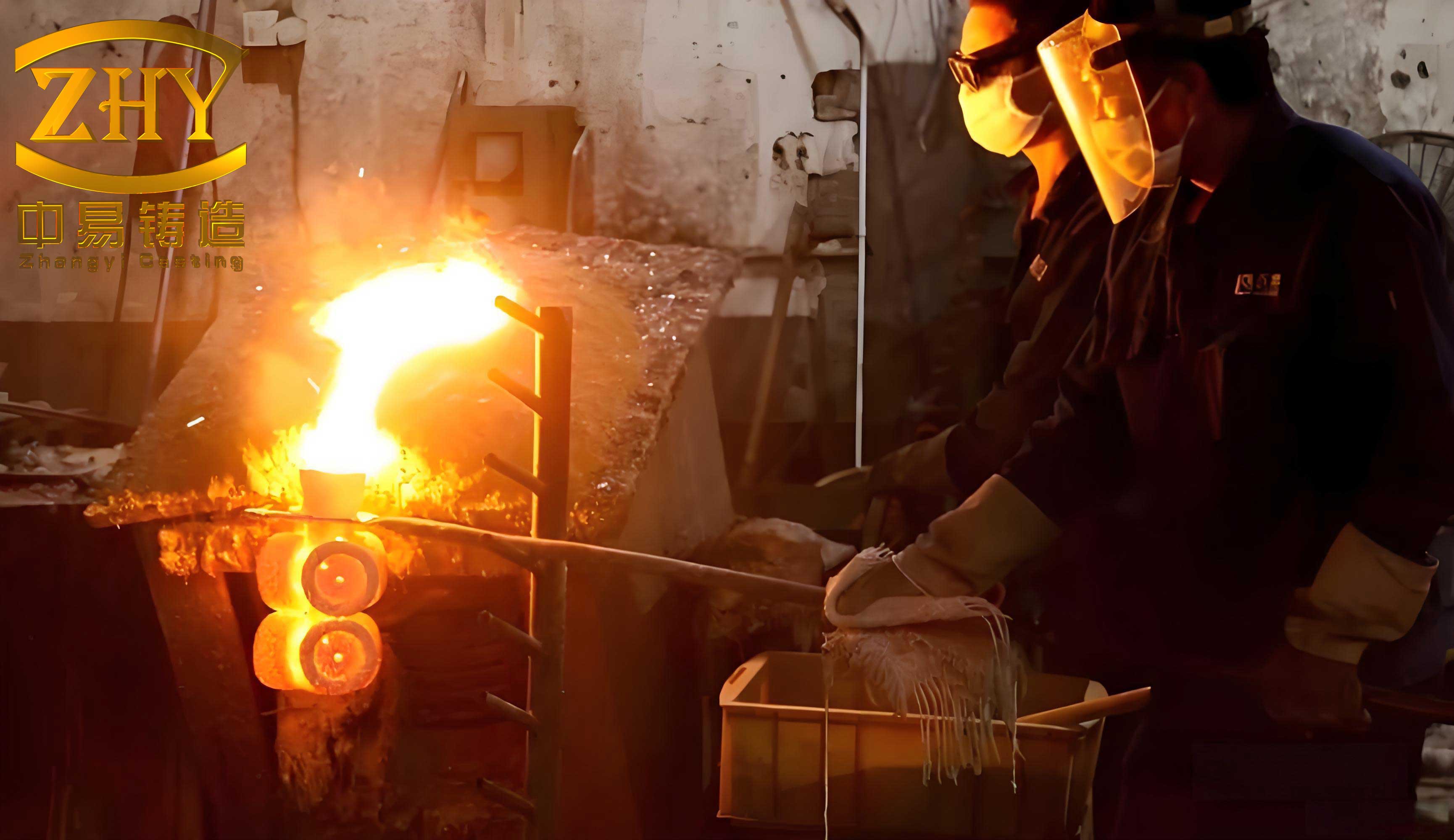
Investment casting, also known as lost-wax casting, is a precision manufacturing process capable of producing complex, near-net-shape components with excellent surface finish and dimensional accuracy. The process begins with the fabrication of a wax pattern, which is then assembled into a cluster with a gating system. This assembly is repeatedly coated with ceramic slurry to build a robust shell. After dewaxing and high-temperature firing, the resulting ceramic mold is ready for molten metal pouring. Upon solidification, the shell is removed, and the castings are separated from the gating system. This technique is particularly suitable for components requiring intricate geometries and high integrity, such as the bimetallic connecting rods in our research. The following image illustrates the precision achievable through advanced investment casting processes.
The success of investment casting for bimetallic parts heavily relies on the design of the gating and feeding system to ensure proper metal flow, sequential solidification, and defect-free castings. In our case, the primary challenge is to achieve a sound metallurgical bond between the steel matrix and the pre-placed cast iron insert while avoiding internal defects. Numerical simulation has become an indispensable tool for optimizing such processes. We employed ProCAST, a powerful finite element-based software, to simulate the filling, solidification, and cooling stages of the bimetallic connecting rod investment casting. The goal was to compare two gating system designs—top gating and side gating—and identify the configuration that minimizes shrinkage defects.
Numerical Simulation Methodology
Our simulation workflow began with the creation of a three-dimensional model of the bimetallic connecting rod and its gating system. The connecting rod featured a big end diameter of 60 mm, a thickness of 20 mm, and a cast iron insert with dimensions of 80 mm in length, 20 mm in thickness, and 5 mm in width. Two distinct gating systems were modeled: a top-gating system where metal enters from above the casting, and a side-gating system where metal enters from the side. These models were then discretized into finite element meshes using preprocessing tools. The mesh included both the casting and the ceramic shell to account for heat transfer across the interface. The table below summarizes the key components and their respective materials used in the simulation.
| Component | Material | Initial Temperature (°C) | Remarks |
|---|---|---|---|
| Connecting Rod Main Body | AISI 1026 Low Carbon Steel | 1600 (Pouring Temperature) | Primary structural material |
| Fracture Zone Insert | GJL-250 Gray Cast Iron | 400 | Pre-placed brittle material |
| Ceramic Mold Shell | Zircon Sand | 1150 | Refractory material for investment casting |
The thermal and physical properties of these materials are critical for accurate simulation. ProCAST utilizes a database of material properties, but we can express the fundamental heat transfer governing equation as follows. The general heat conduction equation during solidification is given by:
$$ \rho c_p \frac{\partial T}{\partial t} = \nabla \cdot (k \nabla T) + Q_{latent} $$
where \( \rho \) is density, \( c_p \) is specific heat, \( T \) is temperature, \( t \) is time, \( k \) is thermal conductivity, and \( Q_{latent} \) represents the latent heat release due to phase change. For the investment casting process, the boundary conditions at interfaces are paramount. We defined the interfacial heat transfer coefficients (HTC) as follows:
- HTC between steel main body and ceramic shell: 1000 W/(m²·K)
- HTC between cast iron insert and ceramic shell: 500 W/(m²·K)
- HTC between steel and cast iron insert: 3000 W/(m²·K)
The higher HTC at the bimetallic interface assumes good contact and promotes metallurgical bonding. The pouring process was simulated as gravity pouring with a fill time of 3 seconds. After pouring, natural air cooling was applied. The simulation outputs included temperature distribution, solidification sequence, and defect prediction based on criteria like Niyama criterion for shrinkage porosity. The Niyama criterion is often expressed as:
$$ N_y = \frac{G}{\sqrt{\dot{T}}} $$
where \( G \) is the temperature gradient and \( \dot{T} \) is the cooling rate. Regions with \( N_y \) below a critical value are prone to shrinkage porosity.
Simulation Results and Analysis
We conducted separate simulations for the top-gating and side-gating investment casting systems. The results were analyzed in terms of solidification time contours and predicted defect regions. The table below provides a comparative summary of the key findings.
| Aspect | Top-Gating System | Side-Gating System |
|---|---|---|
| Solidification Sequence | Riser and rod shank solidify first; big end and pouring cup solidify last. | Connecting rod body solidifies before the gating system; sprue solidifies last. |
| Shrinkage Defect Location | Pronounced defects in pouring cup, big end of rod, and riser. | Defects confined to the sprue; rod body is free of defects. |
| Riser Effectiveness | Ineffective as it solidifies early, failing to feed the casting. | Sprue acts as an effective feeder, compensating for solidification shrinkage. |
| Overall Soundness | Poor; defects within critical casting areas. | Excellent; defects only in disposable gating. |
For the top-gating investment casting design, the simulation revealed a non-sequential solidification pattern. The riser and the thinner sections of the rod solidified prematurely, leaving the thermally massive regions like the big end and the pouring cup as last-to-freeze zones. According to the principle of solidification shrinkage, these last-to-freeze areas are susceptible to the formation of macro- and micro-porosity. The defect prediction map clearly highlighted significant shrinkage porosity and holes in the pouring cup, the central web of the connecting rod big end, and the riser itself. This outcome is highly undesirable as defects in the casting body would compromise mechanical integrity and hinder the subsequent裂解 (cracking) process. The governing factors can be related to the thermal modulus. The thermal modulus \( M \) is approximately proportional to the volume-to-surface area ratio:
$$ M \propto \frac{V}{A} $$
Regions with a higher \( M \) solidify slower and require feeding. In the top-gate design, the gating system did not maintain a thermal gradient conducive to directional solidification toward the riser.
In contrast, the side-gating investment casting system demonstrated a markedly different solidification profile. The thermal design of this system promoted directional solidification starting from the extremities of the casting toward the gating system. Specifically, the connecting rod body solidified prior to the sprue. This sequence ensured that the liquid metal in the sprue could continuously feed the shrinking casting until complete solidification. Consequently, the defect prediction indicated that shrinkage porosity was exclusively concentrated within the sprue, which is a part of the gating system to be removed during post-casting processing. The casting itself, including the critical bimetallic interface zone, was predicted to be sound and free from shrinkage defects. The success of this design can be attributed to the controlled heat extraction and the establishment of a positive temperature gradient \( G \) from the casting to the feeder, satisfying the condition for feeding:
$$ G_{casting} > G_{feeder} $$
This ensures that the feeder remains molten longer than the casting, enabling it to fulfill its feeding function effectively.
Theoretical Considerations for Bimetallic Bonding in Investment Casting
A crucial aspect of this bimetallic investment casting process is the formation of a metallurgical bond at the interface between the steel and the pre-placed cast iron insert. The bond strength depends on interdiffusion and possible formation of intermediate phases. The diffusion process can be described by Fick’s laws. For one-dimensional diffusion, the concentration \( C \) over time and position is governed by:
$$ \frac{\partial C}{\partial t} = D \frac{\partial^2 C}{\partial x^2} $$
where \( D \) is the diffusion coefficient, which is temperature-dependent and follows an Arrhenius relationship:
$$ D = D_0 \exp\left(-\frac{Q}{RT}\right) $$
Here, \( D_0 \) is a pre-exponential factor, \( Q \) is the activation energy, \( R \) is the gas constant, and \( T \) is absolute temperature. During the investment casting process, the high pouring temperature of the steel (1600°C) and the preheated state of the cast iron insert (400°C) create a temperature gradient at the interface, promoting atomic diffusion. However, excessive interdiffusion or the formation of brittle intermetallics could be detrimental. Therefore, controlling the thermal history through gating design is essential not only for defect minimization but also for optimizing the interfacial microstructure. The ProCAST simulation provides detailed thermal history data, allowing us to estimate the diffusion depth \( \delta \) using a simplified equation:
$$ \delta \approx \sqrt{D t} $$
where \( t \) is the time available for diffusion at elevated temperatures. A well-designed investment casting process should maintain the interface at a suitable temperature range for an optimal duration to achieve a sound bond without excessive brittle phase formation.
Experimental Validation and Production Process
Based on the simulation results, the side-gating investment casting system was selected for experimental validation. The actual production process meticulously followed the steps of investment casting. First, wax patterns of the connecting rod specimen were produced using injection molding dies. The cast iron inserts were precisely positioned within the wax pattern assembly. Subsequently, the wax patterns and inserts were assembled with the side-gating wax system to form a cluster. This cluster underwent the ceramic shell building process, involving successive dips in zircon-based slurries and stuccoing with refractory grains. After the shell reached sufficient thickness, it was dewaxed in a steam autoclave. The ceramic shell was then fired at a temperature between 1150°C and 1200°C for 40-50 minutes to achieve adequate strength and remove residual volatiles.
The pouring operation was critical. The preheated shell (at ~1150°C) was ready for metal reception. The main body material, 20Cr steel (similar to AISI 1026), was melted and superheated to approximately 1650°C. It was then poured into the shell under gravity. The molten steel flowed through the side-gating system, enveloping the pre-placed cast iron insert. After filling, the assembly was allowed to cool in ambient air. Upon complete solidification, the ceramic shell was knocked off, revealing the cast cluster. The gating system, including the sprue where defects were predicted, was removed by cutting. The resulting bimetallic connecting rod specimen was inspected. Visual and non-destructive examinations confirmed the absence of shrinkage porosity or holes in the casting body. The interface between steel and cast iron appeared continuous and well-bonded. Subsequent heat treatment (quenching and tempering) was performed to achieve the desired mechanical properties in the steel matrix. Finally, the cracking test was conducted on the bimetallic rod, resulting in a clean fracture along the cast iron insert, validating the concept. The table below outlines the key parameters and outcomes of the experimental production run.
| Process Parameter | Value or Observation |
|---|---|
| Wax Pattern Material | Industrial-grade paraffin wax |
| Ceramic Shell Material | Zircon prime coat, silica-based backup coats |
| Shell Firing Temperature | 1175°C (average) |
| Shell Firing Time | 45 minutes |
| Main Body Alloy | 20Cr Steel |
| Pouring Temperature | 1650 ± 10°C |
| Pre-placed Insert Material | GJL-250 Gray Cast Iron |
| Insert Preheat Temperature | 400°C |
| Cooling Method | Still air cooling |
| Gating System Removal | Cut-off grinding |
| Casting Body Quality | Sound, no shrinkage defects detected |
| Bimetallic Interface | Metallurgical bond achieved, no de-lamination |
| Cracking Test Result | Clean fracture through cast iron insert |
Comprehensive Discussion on Process Optimization
The optimization of the investment casting process for bimetallic components extends beyond gating design. Several interconnected factors contribute to the final quality. We can formulate a multi-objective optimization problem where the goal is to minimize defects \( D \), maximize bond strength \( B \), and ensure dimensional accuracy \( A \). These objectives are functions of process variables such as pouring temperature \( T_p \), shell preheat temperature \( T_s \), pouring time \( t_p \), and gating geometry \( G \). Symbolically:
$$ \text{Minimize } D(T_p, T_s, t_p, G), \quad \text{Maximize } B(T_p, T_s, t_p, G), \quad \text{Subject to } A(T_p, T_s, t_p, G) \geq A_{spec} $$
Our study primarily varied \( G \) (gating geometry) while keeping other parameters within standard ranges for steel investment casting. The success of the side-gating system can be analyzed through thermal analysis. The solidification time \( t_f \) for a region can be estimated using Chvorinov’s rule:
$$ t_f = C \left( \frac{V}{A} \right)^n $$
where \( C \) is a constant dependent on mold material and metal properties, and \( n \) is an exponent (typically ~2). For sequential solidification, we need:
$$ t_{f,\text{casting}} < t_{f,\text{feeder}} $$
The side-gating design, by altering the volume-to-surface area ratio \( V/A \) of the feeder (sprue) relative to the casting, ensured this inequality held true. Furthermore, the investment casting shell acts as a significant thermal barrier. The heat flux \( q” \) across the shell during solidification is given by:
$$ q” = h (T_{\text{metal}} – T_{\text{shell,outer}}) $$
where \( h \) is the effective heat transfer coefficient. A side-gating system can promote more uniform heat extraction compared to a top-gating system, reducing thermal stresses and hot spots.
Another critical consideration is the feeding distance in investment casting. For a sound casting, the feeding distance \( L_f \) from a feeder must be sufficient to cover the entire casting. Empirical rules often relate \( L_f \) to the section thickness \( d \). For steel castings, a common rule is \( L_f \approx 4.5d \) for end-fed sections. Our connecting rod design, with its varying cross-sections, required careful placement of the gate to ensure all regions were within the effective feeding range of the sprue. The simulation confirmed that the side gate location achieved this.
The role of the ceramic shell in investment casting cannot be overstated. Its thermal properties directly influence the cooling rate. The effective thermal conductivity \( k_{eff} \) of a multi-layered ceramic shell is complex but can be approximated for steady-state one-dimensional heat flow as:
$$ \frac{1}{k_{eff}} \approx \frac{1}{k_1} + \frac{1}{k_2} + \ldots $$
for series resistance, where \( k_1, k_2, \ldots \) are conductivities of individual layers. A shell with lower effective conductivity slows cooling, which can be beneficial for feeding but may coarsen the microstructure. Our use of zircon sand for the primary coat provided a good balance of high refractoriness and suitable thermal properties.
Extended Applications and Future Directions
The methodology presented here—combining numerical simulation with investment casting for bimetallic components—has broad applicability. It can be extended to other engine parts, turbine blades with wear-resistant tips, or tools requiring a hard facing on a tough core. The investment casting process offers the design freedom to incorporate preforms of different materials, enabling functional gradation. Future work could involve optimizing the composition of the insert material to control the fracture toughness more precisely or exploring other brittle alloys. Additionally, advanced simulation capabilities like modeling microstructure evolution (e.g., phase field method) at the bimetallic interface could be integrated. The phase field equation for a binary system can be expressed as:
$$ \frac{\partial \phi}{\partial t} = M_\phi \left[ \nabla^2 \phi – \frac{\partial f(\phi, C)}{\partial \phi} \right] $$
where \( \phi \) is the phase field variable, \( M_\phi \) is mobility, and \( f \) is the free energy density functional. Such simulations would provide deeper insights into the bonding mechanism during investment casting.
Furthermore, the investment casting process parameters themselves can be optimized using response surface methodology or machine learning algorithms. For instance, a central composite design could be used to model the relationship between factors like pouring temperature, shell preheat, and response variables like shrinkage pore volume or bond strength. This would lead to a more robust and optimized investment casting process for mass production.
Conclusion
Through comprehensive numerical simulation and experimental verification, we have successfully optimized the investment casting process for manufacturing bimetallic cracking connecting rods. The key finding is that a side-gating investment casting system far outperforms a top-gating system for this specific application. The side-gating design promotes directional solidification, with the casting solidifying before the gating system, thereby confining shrinkage defects to the disposable sprue. The actual castings produced using the optimized investment casting parameters were free of internal defects in the functional areas and exhibited a sound metallurgical bond at the steel-cast iron interface. This validates the effectiveness of simulation-driven design in investment casting. The principles established—regarding thermal gradient control, feeding path design, and interface management—are widely applicable to the investment casting of complex, multi-material components. As investment casting technology continues to evolve, its synergy with advanced simulation tools will undoubtedly unlock new possibilities for manufacturing high-performance engineered parts.