
In the realm of marine engineering, the propeller shaft bracket, often referred to as the stern tube bracket or shaft strut, is a critical component that ensures the efficient transmission of propulsion forces from the engine to the propeller. As a designer with extensive experience in marine systems, I have consistently emphasized the importance of optimizing these components for strength, durability, and hydrodynamic efficiency. The complexity of forces acting on the bracket during vessel operation—including horizontal thrust, vertical lift, unbalanced moments from propeller rotation, and localized vibrations—demands a robust design approach. Moreover, the bracket must withstand extreme scenarios, such as the sudden fracture of one or two propeller blades at maximum RPM, where centrifugal forces can become catastrophic. To address these challenges, steel casting has emerged as the preferred manufacturing method due to its flexibility in shaping, isotropic mechanical properties, and ability to handle complex stress patterns. This article delves into the design and technical specifications of a streamlined propeller shaft bracket for a passenger ro-ro vessel, highlighting the pivotal role of steel casting in marine applications. I will provide detailed insights into the profile shaping, material requirements, and quality assurance protocols, supported by tables and formulas to encapsulate key data. The goal is to offer a comprehensive guide that enhances the performance and reliability of marine propulsion systems through advanced steel casting techniques.
The hydrodynamic performance of a vessel is significantly influenced by the design of underwater appendages, with the propeller shaft bracket being a prime contributor to overall resistance. A poorly designed bracket can lead to increased power loss, excessive vibration, and compromised sailing efficiency. In my practice, I adhere to the principle that an optimally designed bracket should not exceed 4% to 8% of the bare hull resistance. Achieving this requires a streamlined profile that minimizes drag while maintaining structural integrity. The use of steel casting allows for the creation of such complex, fluid-dynamic shapes without compromising on strength. For instance, the bracket arms can be fashioned into aerofoil-like sections inspired by the NACA airfoil series, which are renowned for their low-drag characteristics. This approach not only reduces resistance but also enhances the bracket’s ability to withstand multidirectional loads. In the following sections, I will outline a specific design methodology, starting with the profile definition and extending to the material science behind steel casting for marine environments.
To begin, the profile of the bracket arm is derived from the NACA 022 airfoil, a symmetric profile that offers balanced hydrodynamic properties. The coordinates, or offsets, define the shape from the leading edge to the trailing edge, ensuring a smooth transition that mitigates turbulence. Below is a table presenting the normalized values for a half-profile, which can be scaled according to the bracket’s dimensions. In my design for the passenger ro-ro vessel, these values were applied to create a bracket with a maximum thickness of 55 mm at 30% of the chord length, tapering smoothly to the edges. This profile is critical for reducing vortex shedding and pressure drag, common issues in marine components.
| X (Chord Fraction) | Y (Thickness Fraction) |
|---|---|
| 0.00 | 0.000 |
| 0.01 | 0.033 |
| 0.05 | 0.065 |
| 0.10 | 0.086 |
| 0.15 | 0.098 |
| 0.20 | 0.105 |
| 0.30 | 0.110 |
| 0.40 | 0.106 |
| 0.50 | 0.097 |
| 0.60 | 0.084 |
| 0.70 | 0.067 |
| 0.80 | 0.048 |
| 0.90 | 0.027 |
| 0.95 | 0.015 |
| 1.00 | 0.002 |
These coordinates are derived from the NACA 4-digit series formula, where the thickness distribution is given by:
$$ y_t = \frac{t}{0.2} \left(0.2969\sqrt{x} – 0.1260x – 0.3516x^2 + 0.2843x^3 – 0.1015x^4\right) $$
For the NACA 022 profile, the maximum thickness \(t\) is 22% of the chord, but in our application, it is adjusted to 11% for hydrodynamic optimization. The scaling factor is applied based on the actual chord length of the bracket arm, which in this case is 500 mm. This mathematical model ensures precision in shaping, a hallmark of effective steel casting design. The ability to replicate such intricate geometries is a key advantage of using cast steel over forged alternatives, as it allows for seamless integration of curves and transitions that are essential for flow efficiency.
Moving beyond the profile, the material selection for the bracket is paramount. In marine environments, components are exposed to cyclic loading, corrosion, and low temperatures, necessitating a material with high toughness and fatigue resistance. Steel casting fulfills these requirements due to its homogeneous microstructure and adaptability to alloying. The bracket for this vessel is fabricated from hull structural cast steel, which complies with international standards for marine applications. The chemical composition of the cast steel must be carefully controlled to achieve the desired mechanical properties. Below is a table summarizing the permissible ranges for key elements, as derived from my experience and industry norms.
| Element | Minimum | Maximum | Notes |
|---|---|---|---|
| C (Carbon) | – | 0.23 | May exceed if carbon equivalent ≤ 0.41% |
| Mn (Manganese) | 3 × C content | 1.60 | Enhances strength and toughness |
| Si (Silicon) | – | 0.60 | Deoxidizer, improves fluidity |
| P (Phosphorus) | – | 0.04 | Impurity, reduces ductility |
| S (Sulfur) | – | 0.04 | Impurity, promotes hot shortness |
| Cu (Copper) | – | 0.30 | Residual, improves corrosion resistance |
| Cr (Chromium) | – | 0.30 | Residual, enhances hardenability |
| Ni (Nickel) | – | 0.40 | Residual, improves low-temperature toughness |
| Mo (Molybdenum) | – | 0.15 | Residual, increases strength at high temperatures |
| Total Residuals | – | 0.80 | Sum of Cu, Cr, Ni, Mo |
The carbon equivalent (CE) is a critical parameter for weldability and is calculated using the formula:
$$ \text{CE} = \text{C} + \frac{\text{Mn}}{6} + \frac{\text{Cr} + \text{Mo} + \text{V}}{5} + \frac{\text{Ni} + \text{Cu}}{15} $$
For this steel casting, the CE must not exceed 0.41% to prevent cracking during welding and ensure adequate toughness. This formula underscores the importance of balancing alloying elements in cast steel to achieve optimal performance. In my designs, I often specify that manganese content should be at least three times the carbon content to enhance hardenability and impact resistance, which is crucial for components subjected to dynamic sea loads.
Heat treatment is another vital aspect of steel casting processing. For the bracket, which weighs approximately 1.6 tons, a normalizing and tempering cycle is employed. Normalizing involves heating the cast steel to a temperature between 900°C and 970°C, followed by air cooling. This refines the grain structure, eliminates casting stresses, and homogenizes the microstructure. Tempering is then conducted at 600°C to 620°C to relieve residual stresses and improve toughness. The process can be represented by the following kinetic equation for grain growth during normalizing:
$$ D^n – D_0^n = k t \exp\left(-\frac{Q}{RT}\right) $$
where \(D\) is the final grain size, \(D_0\) is the initial grain size, \(n\) is a time exponent, \(k\) is a constant, \(t\) is time, \(Q\) is the activation energy, \(R\) is the gas constant, and \(T\) is the absolute temperature. In practice, I limit re-heat treatments to two cycles (excluding tempering) to avoid excessive grain coarsening, which can degrade mechanical properties. This controlled approach ensures that the steel casting achieves a balance of strength and ductility suitable for marine service.
The mechanical properties of the cast steel are validated through standardized testing. Test coupons are cast alongside the bracket from the same heat of steel and subjected to identical heat treatment. These coupons are used to prepare tensile and impact specimens. The required mechanical performance is outlined in the table below, which I have compiled based on industry standards and project-specific demands.
| Property | Symbol | Minimum Value | Notes |
|---|---|---|---|
| Tensile Strength | \(R_m\) | 400 MPa | Upper limit: 550 MPa |
| Yield Strength | \(R_{eH}\) | 200 MPa | Measured at 0.2% offset |
| Elongation | \(A_5\) | 25% | Over 5× gauge length |
| Reduction of Area | \(Z\) | 40% | Indicates ductility |
For intermediate tensile strengths, interpolation is used to determine the corresponding minima for yield strength, elongation, and reduction of area. This ensures a graded approach to material selection. Additionally, Charpy V-notch impact testing is mandated for welded structures to assess toughness. Specimens are taken from a quarter-thickness location in the test coupon and tested at 0°C. The energy absorption must be at least 27 J, as per the formula for impact energy correlation:
$$ E = \frac{1}{2} m v^2 $$
where \(E\) is the impact energy, \(m\) is the mass of the pendulum, and \(v\) is the velocity at impact. This test is critical for steel casting in cold environments, where brittle fracture is a concern. In my experience, meeting these impact requirements often necessitates fine-tuning the heat treatment parameters, particularly the tempering temperature and cooling rate.
Quality assurance in steel casting involves rigorous inspection protocols. The bracket must be produced to a 1:1 scale, with all mounting holes and channels machined post-casting. Surface and internal integrity are assessed through visual examination and non-destructive testing (NDT). Surface roughness is controlled to Ra ≤ 12.5 μm for cast surfaces and Ra ≤ 6.3 μm for the shaft hub, adhering to standard benchmarks. Weight tolerance is set at MT 10 level, with a ±3% deviation, ensuring consistency across production batches. The following table summarizes the acceptance criteria for magnetic particle inspection (MPI), a key NDT method for detecting surface and near-surface flaws.
| Inspection Area | Cracks | Linear Indications | Non-linear Indications |
|---|---|---|---|
| Weld Preparation Surfaces | Not Permitted | ≤ 2 mm | ≤ 3 mm |
| Critical Zones (e.g., arm-root junctions) | Not Permitted | ≤ 2 mm | ≤ 6 mm |
| Other Areas | Not Permitted | ≤ 2 mm | ≤ 10 mm |
Ultrasonic testing (UT) is also employed post-heat treatment to identify internal discontinuities. If defects are found, they are removed by grinding or gouging, and the areas are repaired by welding. The weld repair process uses low-hydrogen electrodes baked at 300–350°C for over an hour to minimize hydrogen-induced cracking. The weld metal must match or exceed the base metal’s mechanical properties, as verified by additional UT after stress relief annealing at 550–650°C for 30 minutes. This holistic approach to defect management is essential for maintaining the integrity of steel casting components in demanding marine applications.
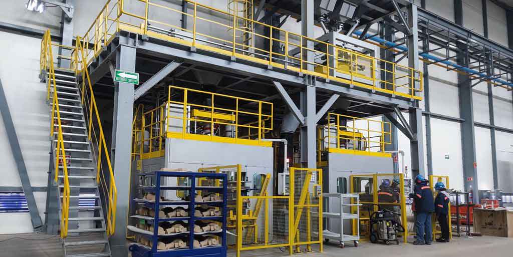
The manufacturing environment for such steel casting components relies on advanced equipment to ensure precision and quality. From melting furnaces to molding stations, each stage must be optimized for the production of marine-grade castings. Below is an image depicting typical steel casting equipment used in modern foundries, highlighting the scale and technology involved. This visual underscores the industrial context in which these brackets are produced, emphasizing the synergy between design and manufacturing.
In addition to the technical specifications, the design of the propeller shaft bracket must account for hydrodynamic interactions with the hull and propeller. The resistance contributed by the bracket can be estimated using the formula for appendage resistance:
$$ R_{\text{appendage}} = C_f \cdot \frac{1}{2} \rho V^2 S $$
where \(C_f\) is the frictional coefficient, \(\rho\) is the water density, \(V\) is the vessel speed, and \(S\) is the wetted surface area of the bracket. For streamlined profiles, \(C_f\) can be reduced by up to 30% compared to bluff shapes, directly lowering power consumption. In my designs, I often use computational fluid dynamics (CFD) simulations to optimize the bracket’s shape iteratively, ensuring that the resistance stays within the 4–8% target. This involves solving the Navier-Stokes equations for turbulent flow around the bracket:
$$ \rho \left( \frac{\partial \mathbf{u}}{\partial t} + \mathbf{u} \cdot \nabla \mathbf{u} \right) = -\nabla p + \mu \nabla^2 \mathbf{u} + \mathbf{f} $$
where \(\mathbf{u}\) is the velocity field, \(p\) is pressure, \(\mu\) is dynamic viscosity, and \(\mathbf{f}\) represents body forces. These simulations validate the empirical data from the NACA profile and guide adjustments in the steel casting design to minimize drag.
The structural analysis of the bracket under load is equally important. Using finite element analysis (FEA), I model the stress distribution due to combined thrust, lift, and moment loads. The von Mises stress criterion is applied to assess yielding:
$$ \sigma_{\text{von Mises}} = \sqrt{ \frac{(\sigma_1 – \sigma_2)^2 + (\sigma_2 – \sigma_3)^2 + (\sigma_3 – \sigma_1)^2 }{2} } $$
where \(\sigma_1, \sigma_2, \sigma_3\) are the principal stresses. For the cast steel material, the von Mises stress must remain below the yield strength of 200 MPa under normal operating conditions, and below the ultimate tensile strength of 400 MPa under extreme loads like blade loss. This analysis informs the placement of reinforcing ribs and thickness variations in the steel casting, ensuring a factor of safety greater than 1.5. The ability of cast steel to accommodate such tailored thickness transitions is a key advantage over wrought products, which may have directional weaknesses.
Corrosion resistance is another critical factor for marine steel casting. The bracket is typically coated with epoxy paints or cathodic protection systems, but the base material must also resist general and pitting corrosion. The addition of copper and chromium residuals in the alloy improves corrosion performance, as quantified by the pitting resistance equivalent number (PREN):
$$ \text{PREN} = \text{Cr} + 3.3 \cdot \text{Mo} + 16 \cdot \text{N} $$
For this cast steel, the PREN is relatively low due to minimal alloying, but it suffices for brackish water environments when combined with protective coatings. In more aggressive conditions, I specify higher alloy steel casting grades, such as duplex stainless steels, though they come at a higher cost. The selection always balances economic and performance criteria.
The production of the bracket involves pattern making, molding, melting, pouring, and finishing. The pattern is crafted from wood or plastic to the exact profile coordinates, accounting for shrinkage allowances typical of steel casting, which range from 2% to 2.5%. The molding process uses resin-bonded sand to capture fine details, and the melt is prepared in electric arc furnaces for precise temperature control. Pouring temperature is maintained at approximately 1600°C to ensure fluidity and minimize defects. The solidification time \(t_s\) can be estimated using Chvorinov’s rule:
$$ t_s = k \left( \frac{V}{A} \right)^n $$
where \(V\) is the volume, \(A\) is the surface area, and \(k\) and \(n\) are constants dependent on the mold material. For the bracket, with its varying cross-sections, controlled cooling is essential to avoid shrinkage porosity, a common challenge in steel casting. This is managed through strategic placement of risers and chills in the mold design.
Post-casting, the bracket undergoes shot blasting to remove residual sand and scale, followed by machining of critical interfaces like the shaft bore and mounting surfaces. Dimensional checks are performed using coordinate measuring machines (CMMs) to verify conformity to the design tolerances. The bracket is then marked with identifying information such as heat number and classification society stamp, but as per the guidelines, specific identifiers like names and addresses are omitted in this discussion. This traceability is vital for quality control in steel casting supply chains.
In service, the performance of the bracket is monitored through vibration analysis and periodic inspections. The natural frequency of the bracket should be outside the excitation frequencies from propeller rotation to avoid resonance. This is calculated using the formula for a cantilever beam approximation:
$$ f_n = \frac{1}{2\pi} \sqrt{\frac{k}{m}} $$
where \(k\) is the stiffness and \(m\) is the mass. For the streamlined design, the added mass of water affects the dynamics, requiring coupled fluid-structure interaction analyses. Regular underwater inspections check for cracks, corrosion, or biofouling that could compromise the steel casting integrity. Any defects found are assessed against the repair protocols outlined earlier, ensuring continuous reliability.
To further elaborate on the material science aspect, the microstructure of the cast steel is examined using metallography. The typical as-cast structure consists of ferrite and pearlite, which is refined through normalizing to a fine-grained ferrite-pearlite matrix. The impact of alloying elements on hardenability is described by the ideal critical diameter \(D_I\) formula:
$$ D_I = D_{\text{base}} \times \text{MF} $$
where \(D_{\text{base}}\) is the base diameter for plain carbon steel and MF is a multiplicative factor based on composition. For the specified cast steel, the moderate levels of manganese and silicon provide sufficient hardenability for the bracket’s thickness without necessitating quenching. This balance is crucial for avoiding distortion and residual stresses in the steel casting.
The economic implications of using steel casting for marine brackets are also noteworthy. While the initial tooling cost for patterns is higher than for fabrications, the per-unit cost decreases with volume, making it economical for series production. Moreover, the reduced machining requirement due to near-net-shape casting lowers labor and material waste. In life-cycle assessments, cast steel brackets demonstrate longer service intervals and lower maintenance costs compared to welded assemblies, which are prone to fatigue cracks at joints. This makes steel casting a sustainable choice for the marine industry.
In conclusion, the design and manufacturing of a propeller shaft bracket for marine vessels involve a multifaceted approach that integrates hydrodynamic shaping, material engineering, and rigorous quality control. The use of steel casting enables the realization of complex, streamlined profiles that minimize resistance while withstanding severe operational loads. Through detailed specifications for chemistry, heat treatment, mechanical properties, and inspection, I ensure that each bracket meets the highest standards of performance and safety. The tables and formulas presented here serve as a reference for engineers and foundries engaged in marine steel casting projects. As vessel designs evolve towards greater efficiency and sustainability, the role of advanced steel casting techniques will only expand, driving innovation in marine component manufacturing. By adhering to these principles, we can achieve brackets that not only support propulsion systems reliably but also contribute to the overall energy efficiency of the vessel, aligning with global trends in green shipping.
To recap, the key takeaways include: the importance of NACA-based profiles for drag reduction, the criticality of carbon equivalent control for weldability, the necessity of Charpy impact testing for toughness assurance, and the comprehensive defect management protocols for steel casting integrity. Each of these elements underscores the synergy between design and material science in marine engineering. As I continue to refine these methodologies, I am committed to pushing the boundaries of what is possible with steel casting, ensuring that marine components are not only functional but also optimized for the challenges of the open sea. The future may see increased adoption of simulation-driven design and additive manufacturing for patterns, but the core principles of quality steel casting will remain indispensable.