
In my extensive experience with investment casting, particularly for precision components, I have often encountered challenging surface defects that compromise product quality. Among these, the mechanical pitting and pockmark defects on 400 series stainless steel castings are particularly pervasive and damaging. Investment casting, also known as lost-wax casting, is a sophisticated manufacturing process renowned for producing complex, high-quality metal parts with excellent surface finish and dimensional accuracy. However, when applied to alloys like 400 series stainless steels—which include grades such as 410, 420, 430, and 431—the process can be plagued by surface oxidation issues leading to these defects. These imperfections, appearing as small hemispherical pits or craters, render castings unusable for applications demanding high surface integrity, such as medical devices, aerospace components, or decorative hardware. Through systematic investigation and process innovation, I have developed and validated a method to mitigate these defects effectively, enhancing the reliability and efficiency of investment casting for these materials.
The core of the problem lies in the inherent reactivity of 400 series stainless steels during the investment casting process. These alloys are ferritic or martensitic stainless steels with significant chromium content (typically 11-30% Cr) but lower nickel compared to austenitic grades. This composition makes them prone to oxidation at high temperatures, especially when exposed to oxygen during pouring and solidification. In investment casting, the molten metal is poured into a ceramic shell mold built around a wax pattern. After pouring, the metal cools and solidifies within the shell, which is later removed. Any interaction between the hot metal and oxidizing agents—whether from the atmosphere, the shell materials, or impurities—can trigger surface defects.
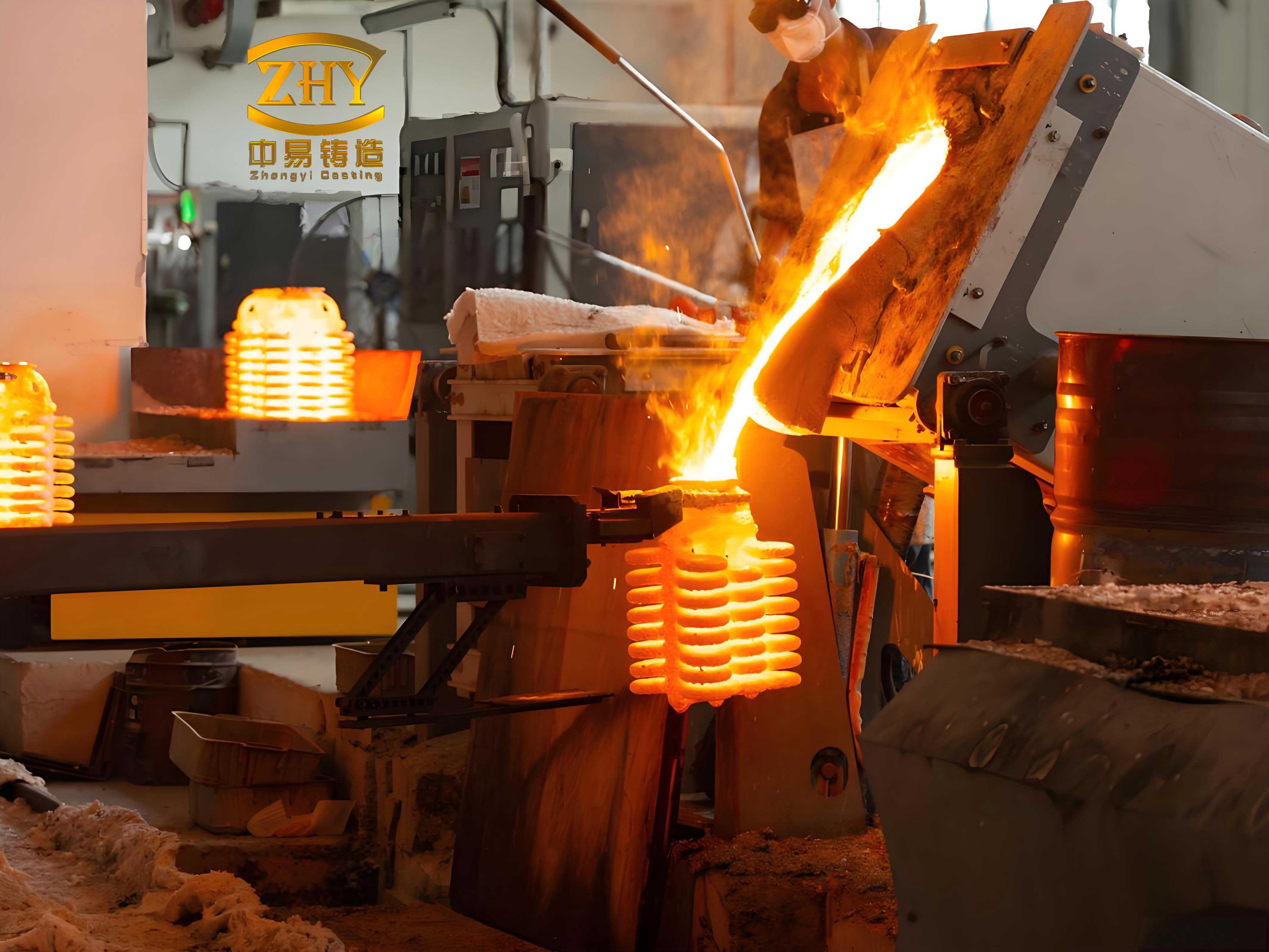
To understand the defect mechanisms, I conducted detailed analyses of affected castings. Mechanical pitting defects typically manifest as numerous small, round pits with diameters ranging from 0.3 to 0.8 mm and depths of 0.3 to 0.5 mm, often clustered in localized areas. Spectroscopic examination reveals that these pits are rich in metal oxides, primarily iron and chromium oxides. Pockmark defects, on the other hand, are associated with slag inclusions and show altered metal composition, such as increased silicon and depleted manganese. X-ray diffraction studies confirm that the black spots consist of magnetite (Fe3O4) and iron-chromium spinel (FeO·Cr2O3). The formation pathways involve complex high-temperature reactions. For instance, during shell firing, impurities like Fe3O4 in the refractory materials can react with silica (SiO2) to form low-melting-point ferrous silicate (FeO·SiO2), which migrates to the shell surface. Upon contact with molten steel, this silicate interacts with chromium oxide (Cr2O3) from the metal oxidation, producing high-melting-point, viscous iron-chromium spinel that adheres to the casting surface, resulting in pockmarks. The key chemical reactions can be summarized as follows:
$$ \text{FeO} + \text{SiO}_2 \rightarrow \text{FeO} \cdot \text{SiO}_2 \quad \text{(formation of ferrous silicate)} $$
$$ 4\text{Cr} + 3\text{O}_2 \rightarrow 2\text{Cr}_2\text{O}_3 \quad \text{(oxidation of chromium)} $$
$$ \text{FeO} + \text{Cr}_2\text{O}_3 \rightarrow \text{FeO} \cdot \text{Cr}_2\text{O}_3 \quad \text{(formation of iron-chromium spinel)} $$
Traditional approaches in investment casting to combat these defects have focused on controlling process variables and material purity. Common strategies include using clean, dry charge materials; reducing pouring and mold temperatures to minimize oxidation time; and employing post-pouring techniques like “boxing” or “capping”—covering the hot shell with a protective container to create a reducing atmosphere. However, these methods have limitations. Boxing is labor-intensive, environmentally taxing (due to smoke from burned materials), and inconsistent if seals are imperfect. Moreover, it does not address oxidation from shell impurities. Lowering temperatures risks cold shuts or misruns. Thus, a more robust solution was needed within the investment casting framework.
I hypothesized that modifying the shell-building process itself could provide a sustained protective environment. The innovation involved incorporating a layer of graphite sand into the ceramic shell. Graphite is an excellent refractory material with high thermal stability, low thermal expansion, and the ability to generate a reducing atmosphere at elevated temperatures. Specifically, I replaced the third layer of the standard shell (typically made of mullite sand) with synthetic graphite sand of similar granulometry. This graphite layer acts as a barrier: it intercepts oxygen from the atmosphere and prevents migration of oxidizing impurities from the backup layers. At high temperatures, graphite oxidizes to carbon monoxide (CO), which envelops the metal-shell interface in a reducing environment, inhibiting the formation of metal oxides. The effectiveness of graphite in investment casting stems from its properties, as outlined in the table below:
| Property | Value/Range | Benefit in Investment Casting |
|---|---|---|
| Fixed Carbon Content | ~99.5% | High purity minimizes additional impurities |
| Oxidation Onset | >400°C | Stable during shell drying and initial firing |
| Oxidation Product at >1000°C | CO (carbon monoxide) | Creates reducing atmosphere at pouring temperatures |
| Linear Expansion Coefficient | ~2 × 10⁻⁶ /°C | Excellent thermal shock resistance, prevents shell cracking |
| Ash Content | <0.5% | Low residue reduces risk of inclusion defects |
To validate this approach, I designed a comparative study using a representative 400 series stainless steel component—a hook for outdoor sports equipment made from grade 431. This part requires heat treatment (annealing, quenching, and tempering) to achieve mechanical properties: hardness HRC 28-36, yield strength ≥590 MPa, and tensile strength ≥780 MPa. Surface finish must be suitable for acid washing, wire drawing, polishing, shot peening, and zinc plating, with strict salt-spray corrosion resistance. Any surface defect like pitting would lead to rejection.
The investment casting process for this study followed standard steps: wax pattern assembly, shell building, dewaxing, firing, melting, pouring, and cleaning. Two shell schemes were compared:
| Shell Layer | Standard Scheme (Scheme 2) | Graphite-Enhanced Scheme (Scheme 1) |
|---|---|---|
| Primary (Face) | Zircon sand, 80/120 mesh | Zircon sand, 80/120 mesh |
| Secondary | Mullite sand, 30/60 mesh | Mullite sand, 30/60 mesh |
| Tertiary | Mullite sand, 30/60 mesh | Graphite sand, 30/60 mesh |
| Fourth | Mullite sand, 16/30 mesh | Mullite sand, 16/30 mesh |
| Fifth | Mullite sand, 16/30 mesh | Mullite sand, 16/30 mesh |
All other parameters were kept identical: the same wax tree design (12 pieces per cluster), silica sol binder system, drying conditions, dewaxing in steam autoclave, and shell firing at 1050°C. For melting, I used pre-cleaned charge materials (shot-blasted to remove rust) and controlled deoxidation with silicon, ferrosilicon, and manganese. Pouring temperature was maintained at 1630-1640°C. The key variation was in post-pouring handling: Scheme 2 shells were subjected to boxing with a steel cover after pouring (a traditional method to create a reducing atmosphere), while Scheme 1 shells were left uncovered, relying solely on the graphite layer for protection.
The results were striking. For Scheme 2 (standard shells with boxing), success depended heavily on the seal integrity. If the boxing was loose, oxygen ingress caused visible oxidation on the shell surface (a reddish tint) and corresponding pitting defects on castings. With tight boxing, castings were mostly defect-free, but the method was unreliable and laborious. In contrast, Scheme 1 (graphite-enhanced shells without boxing) consistently produced shells with a uniform grayish-white appearance after pouring, indicating minimal oxidation. Upon cleaning, these castings exhibited smooth, pit-free surfaces. The table below summarizes the visual and quality outcomes:
| Shell Scheme | Post-Pouring Treatment | Shell Surface Color After Pouring | Castings Surface Quality | Defect Rate (Pitting/Pockmarks) |
|---|---|---|---|---|
| Scheme 2 | Loose Boxing | Reddish, signs of oxidation | Severe pitting defects | High (~8% rejection) |
| Scheme 2 | Tight Boxing | Darker, reduced atmosphere | Generally acceptable | Low, but variable |
| Scheme 1 | No Boxing | Grayish-white, uniform | Excellent, no pitting | Negligible (0% in trial) |
Further statistical validation involved a production batch of 1,650 hook castings using the graphite-sand method. Initial inspection revealed zero defects attributable to mechanical pitting or pockmarks. This consistency underscores the reliability of integrating graphite into the investment casting shell system. The method also proved effective for other 400 series grades like 416, demonstrating broad applicability.
Beyond quality improvement, economic analysis revealed significant cost savings. In investment casting, cost factors include material expenses, labor, and scrap losses. For a typical production volume of 1 ton of castings, I compared the costs between the standard and graphite-enhanced processes. The calculations considered shell material costs, labor for boxing, and scrap due to pitting defects. Based on my data:
Let \( C_{\text{total}} \) represent the total cost per ton of castings. For the standard process (Scheme 2):
$$ C_{\text{total, standard}} = C_{\text{shell}} + C_{\text{labor}} + C_{\text{scrap}} $$
Where:
– \( C_{\text{shell}} \) = cost of shell materials (mullite, binder, etc.) = 2,224.26 currency units (e.g., USD).
– \( C_{\text{labor}} \) = labor for boxing operations = 86.4 currency units (based on 0.4 units per cluster × 216 clusters).
– \( C_{\text{scrap}} \) = cost of rejected castings due to pitting = 3,600 currency units (assuming 8% scrap rate at 45 units/kg).
Thus:
$$ C_{\text{total, standard}} = 2224.26 + 86.4 + 3600 = 5910.66 \text{ currency units} $$
For the graphite-enhanced process (Scheme 1):
$$ C_{\text{total, graphite}} = C_{\text{shell, graphite}} + C_{\text{labor, graphite}} + C_{\text{scrap, graphite}} $$
Here:
– \( C_{\text{shell, graphite}} \) = cost of shell materials with graphite sand = 2,510.46 currency units (slightly higher due to graphite).
– \( C_{\text{labor, graphite}} \) = no boxing labor, so = 0.
– \( C_{\text{scrap, graphite}} \) = negligible scrap, assumed = 0.
So:
$$ C_{\text{total, graphite}} = 2510.46 + 0 + 0 = 2510.46 \text{ currency units} $$
The net saving per ton is:
$$ \Delta C = C_{\text{total, standard}} – C_{\text{total, graphite}} = 5910.66 – 2510.46 = 3400.20 \text{ currency units} $$
This 57.5% cost reduction is compelling. Moreover, the elimination of boxing improves workplace conditions by reducing smoke and physical exertion, aligning with sustainable manufacturing practices in investment casting.
The success of graphite sand hinges on its behavior during the investment casting thermal cycle. When the shell is fired and later contacted by molten metal, the graphite in the tertiary layer undergoes controlled oxidation. At temperatures exceeding 1000°C, the reaction:
$$ 2\text{C} + \text{O}_2 \rightarrow 2\text{CO} $$
generates carbon monoxide, which diffuses inward, creating a localized reducing zone at the metal-shell interface. This atmosphere suppresses the oxidation of chromium and iron, thereby preventing the formation of Fe3O4 and FeO·Cr2O3. Concurrently, graphite’s low expansion coefficient ensures shell integrity, avoiding cracks that could exacerbate oxidation. The layered shell structure in investment casting is ideally suited for such functional modifications, allowing targeted placement of reactive materials without compromising overall mold strength.
In practice, implementing this method requires attention to graphite sand specifications. The sand should have high fixed carbon (>99%), low sulfur (<0.03%), and controlled particle size (e.g., 30/60 mesh) to match the shell’s permeability and coating characteristics. During slurry preparation, graphite sand is mixed with silica sol binder similarly to conventional refractories. No special equipment is needed, making it easily adoptable in existing investment casting shops. However, dust control is advisable due to graphite’s black color and fine particles.
Looking broader, this approach illustrates a paradigm shift in defect mitigation for investment casting. Instead of treating symptoms (e.g., post-pouring protection), it addresses root causes by engineering the shell’s chemical environment. This principle could be extended to other alloy systems prone to oxidation, such as titanium or nickel-based superalloys, though compatibility tests would be necessary. Furthermore, the use of computational modeling could optimize graphite layer placement and thickness, potentially reducing material usage while maintaining efficacy.
In conclusion, my investigation confirms that mechanical pitting and pockmark defects in 400 series stainless steel investment castings originate from oxidation interactions involving both atmospheric oxygen and shell impurities. Traditional countermeasures like boxing are inadequate and costly. By integrating a layer of graphite sand into the ceramic shell—specifically as the third layer—the investment casting process gains an intrinsic reducing capability that prevents surface defects consistently. This method eliminates the need for post-pouring boxing, reduces labor, cuts scrap rates to near zero, and yields substantial cost savings. For foundries specializing in investment casting, adopting graphite-enhanced shells for reactive alloys like 400 series stainless steels offers a reliable path to higher quality, productivity, and profitability. As investment casting continues to evolve towards more precise and demanding applications, such material innovations will be crucial for overcoming persistent challenges and unlocking new possibilities in metal component manufacturing.