
In the world of industrial fluid handling, the demands for efficiency, reliability, and precision are ever-increasing. As a casting engineer specializing in complex components, I frequently encounter projects that push the boundaries of conventional foundry practice. Among the most challenging are the single-stage, double-suction, integral volute pump bodies. These are not merely components; they are the very heart of critical pumping systems, often deployed in demanding services like tower bottom pumping in refineries or chemical plants. Their performance hinges on the integrity and accuracy of their steel casting. Today, I will delve into the comprehensive process design for such a component, sharing the methodology and technical considerations that transform a complex blueprint into a robust, reliable casting.
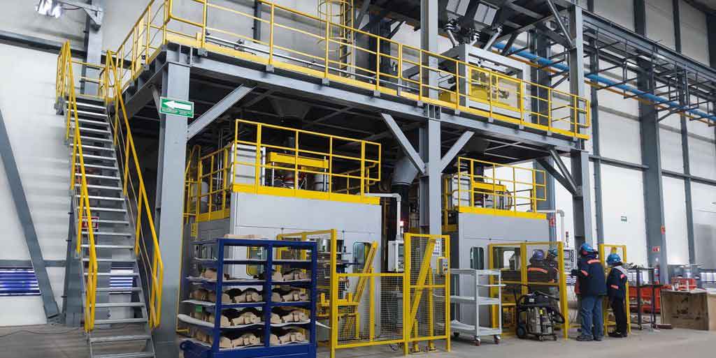
The core challenge of this steel casting lies in its geometry. The pump body is an integral structure, meaning the casing and the cover are cast as one monolithic piece, eliminating the traditional horizontal split line. It features two opposing inlet suction volutes converging into a single, spiraling discharge volute. The material specification is typically a corrosion-resistant austenitic stainless steel, such as ASTM A351 Gr. CF8M, refined via processes like AOD (Argon Oxygen Decarburization) to achieve superior cleanliness and metallurgical control. The casting’s contours are massive, often exceeding 1.5 meters in key dimensions, with a weight measured in tons. However, the wall thickness varies dramatically from nominal sections to heavy flange and foot regions. This disparity, combined with the intricate internal passageways, creates a perfect storm of casting difficulties: isolated thermal hot spots prone to shrinkage, complex coring requirements, and turbulent filling dynamics that can lead to defects.
1. Foundry Methodology and Material Selection
Given the prototype or low-volume nature of such large pump bodies and their geometrical complexity, automated molding lines are impractical. The chosen method is robust, flexible sand casting. We employ a high-quality, chemically-bonded sand system for the molds, typically using furan or phenolic urethane resins for dimensional stability and good collapsibility. For the cores, especially those forming the thin, convoluted, and thermally stressed sections of the volute passages, we mandate the use of chromite sand. Chromite sand’s superior thermal conductivity, high chilling power, and lower thermal expansion compared to silica sand are critical for achieving a sound metallurgical structure, minimizing veining or burn-on defects, and ensuring the surface finish of the flow passages. This choice is a cornerstone in the success of this high-integrity steel casting.
The success of any steel casting project begins with a meticulous feasibility analysis. For the pump body, we break down the challenges and establish key process pillars, as summarized below:
| Process Design Pillar | Primary Challenge | Strategic Solution |
|---|---|---|
| Molding & Coring | Complex internal geometry; maintaining core integrity and dimensional accuracy. | Manual sand molding with resin-bonded sands; extensive use of chromite sand for critical cores; innovative core assembly with定位 features. |
| Parting Line & Orientation | Maximizing feed efficiency and simplifying molding/core setting. | Parting on the discharge volute centerline; detailed analysis of浇注 position (driven-end-up vs. non-driven-end-up). |
| Gating System | Avoiding turbulent filling and oxide inclusion formation in a large, complex cavity. | Bottom-gating through multiple ingates; calculated to control velocity and ensure minimum rise rate. |
| Feeding (Risering) System | Feeding dispersed, isolated hot spots in an irregular shape. | Strategic placement of risers on thick sections (feet); use of feeder heads and chills; leveraging the casting’s own geometry as feeding channels. |
| Dimensional Control | Accounting for differential shrinkage (free vs. restrained contraction). | Application of non-uniform patternmaker’s shrinkage allowances (e.g., internal cores vs. external contours). |
| Finishability | Ensuring all internal flow passages are accessible for grinding to achieve hydraulic smoothness. | Design and simulation of strategically placed clean-out/process holes. |
2. Defining the Parting Line and Casting Orientation
The first major decision is the parting line. For this geometry, the most logical and practical location is along the centerline plane of the discharge volute. This allows the pattern to be drafted cleanly from the mold. However, this defines two possible浇注 positions for the casting: with the larger, driven-end flange oriented upwards, or with the non-driven-end flange upwards. A detailed evaluation is necessary.
Option A: Driven-End-Up Orientation. This scheme places the larger flange and the pump feet in the drag (bottom mold). The primary advantage is core stability. The suction volute cores can seat on a larger, more stable core print in the drag, making the assembly of the complex core package more robust and accurate. This is paramount for achieving the stringent dimensional tolerances required for the flow passages, often to JB/T 6879 Class B levels. The main compromise is that feeding the thick sections of the driven-end flange now requires strategically placed blind risers inside the cavity, accessed through the core assembly.
Option B: Non-Driven-End-Up Orientation. This inverts the casting, placing the large flange at the top in the cope. Feeding becomes straightforward with large top risers directly on the flange. However, the core assembly now rests on a much smaller core print at the driven end, creating a potentially unstable “inverted pyramid” of cores. This significantly increases the risk of core shift or even collapse during molding or pouring, jeopardizing the critical volute dimensions. Furthermore, feeding the driven-end areas becomes more challenging.
The choice is clear in most cases: Option A (Driven-End-Up) is preferred. The integrity and accuracy of the internal water passages are the highest priority for pump performance. We mitigate the feeding challenge for the bottom flange through carefully designed internal side risers. The stability of the core package during the steel casting process is non-negotiable.
3. Core Design and Assembly: Engineering the Negative Space
The internal geometry of the pump is created by an assembly of large, complex sand cores. We design the discharge volute as a single, monolithic core. This is crucial for ensuring the dimensional accuracy and surface continuity of the most critical flow passage. While manufacturing this core is difficult—requiring complex core boxes, careful sand ramming, and potentially auxiliary fill and vent holes—it eliminates parting lines within the volute itself that could cause fins or steps.
The two suction inlets are designed as separate cores. These cores must interface precisely with the monolithic volute core. To achieve this, we incorporate mechanical定位 features, such as interlocking grooves and ridges, into the core prints. This ensures repeatable and accurate assembly, much like a precision puzzle. All core-to-core parting lines are carefully planned to fall in non-critical areas or in locations that can be easily finished.
A critical rule in core design for such a steel casting is to orient the core box’s fill plane to the largest, most open face. For tight sections, we design auxiliary fill holes with a slight taper (wider at the top) to allow foundry personnel to effectively ram sand into every crevice by hand, ensuring uniform core density and strength.
4. The Gating System: A Lesson in Laminar Flow
Pouring several tons of molten stainless steel into such a complex mold is a delicate operation. Turbulence must be minimized to prevent slag entrapment, air aspiration, and mold erosion. Our goal is a quiet, progressive fill. Therefore, a bottom-gating system is mandatory.
The gating system is designed around two key physical parameters: the minimum rise speed of the metal in the cavity, and the maximum entry velocity at the ingates.
- Rise Rate: To prevent cold shuts and allow gases to escape ahead of the advancing metal front, the vertical rise velocity must be sufficient. For a steel casting of this size and section thickness, we target a minimum rise rate (\(V_{rise}\)) of 25 to 30 mm/s. This is calculated based on the pouring time (\(t_p\)) and the height of the casting (\(H_c\)):
$$ V_{rise} = \frac{H_c}{t_p} $$
The required pouring time, in turn, dictates the total choke area of the gating system. - Ingate Velocity: To minimize turbulence at the point of entry, we strive to keep the velocity of the metal through the ingates (\(V_{ingate}\)) below 0.5 m/s. This is governed by Bernoulli’s principle, relating the metallostatic head (\(h\)) and the ingate cross-sectional area (\(A_{ingate}\)) to the flow rate:
$$ V_{ingate} = \frac{\dot{Q}}{A_{ingate}} \approx \frac{\sqrt{2 g h}}{C_d} $$
where \(g\) is gravity and \(C_d\) is a discharge coefficient accounting for system friction.
To satisfy both conditions—a high total flow rate (for rise speed) and a low local velocity (at each ingate)—we employ multiple ingates. Typically, we position one ingate at the base of each internal side riser located in the drag. This serves a dual purpose: it feeds metal quietly into the cavity at multiple points, and it directly heats the riser neck, delaying its solidification and improving feeding efficiency. The system is sized using the principles of hydraulics, treating the sprue, runners, and ingates as a network of conduits. A common starting point is the use of gating ratios to control pressure and flow. For a pressurized system promoting a quiescent fill, a ratio like \( A_{sprue} : A_{runner} : A_{ingate} = 1 : 1.5 : 2 \) might be used as an initial design guideline before simulation.
5. Feeding Strategy: Directing Solidification
The irregular shape of the pump body creates numerous isolated thermal centers—the junctions of flanges, feet, and volute walls. Feeding all of them with individual risers would be impractical and create a nightmare of riser removal and finishing. Instead, we employ a strategic approach that leverages the casting’s own geometry.
A key observation is that the pump feet are thick, rib-like sections that connect the two heavy flange regions. We can design these feet to act as natural feeding channels. By placing a top riser on each foot and applying a taper (padding) towards the critical hot spots, we create a directional solidification path. The riser feeds the foot, and the foot, in turn, feeds the adjacent flange and wall sections. This allows us to feed multiple problematic areas with just two strategically placed risers located on easily accessible, rectangular projections.
The sizing of these risers is critical. We use modulus-based calculations, where the modulus (\(M\)) is the volume-to-surface-area ratio (\(V/A\)), a measure of a section’s solidification time. A riser must have a larger modulus than the region it feeds and contain sufficient volume of liquid metal to compensate for the shrinkage of both the casting section and the riser itself. For a cylindrical top riser, the modulus is approximately \(D/6\) or \(H/4\) (whichever is smaller for a given geometry). We design for a riser modulus (\(M_r\)) that satisfies:
$$ M_r \geq 1.2 \times M_c $$
where \(M_c\) is the modulus of the casting junction being fed. Furthermore, the required riser volume (\(V_r\)) must satisfy the shrinkage demand:
$$ V_r \geq \frac{\varepsilon \cdot V_c}{\eta – \varepsilon} $$
where:
- \(\varepsilon\) is the volumetric shrinkage of the steel alloy (approximately 3-4% for austenitic stainless steels).
- \(V_c\) is the volume of the casting region fed by the riser.
- \(\eta\) is the feeding efficiency of the riser (typically 10-15% for a top riser on a large steel casting).
For hot spots that cannot be effectively reached by these main risers, we use a combination of smaller blind risers (especially inside the cavity on the bottom flange) and judiciously placed chromite sand chills. Chills, with their high thermal conductivity, accelerate local solidification, effectively eliminating the hot spot by turning it into a region that solidifies before the surrounding metal, thus becoming self-feeding.
6. Dimensional Accuracy: Accounting for Differential Shrinkage
A uniform patternmaker’s shrinkage allowance is insufficient for a complex steel casting like this. The contraction of the metal is resisted differently by the mold and cores in various directions. Internally, the dense assembly of sand cores provides massive resistance, significantly restraining contraction. Externally, the mold walls offer less restraint. To achieve casting dimensions within the specified CT11 grade or better, we apply a differential shrinkage rule. For example, dimensions on internal cores (the volute passage diameters) might receive an allowance of only 18-20 mm/m (1.8-2.0%), while external free-contracting dimensions might receive 22-24 mm/m (2.2-2.4%). This is refined based on historical data from similar castings.
7. Process Holes for Finishability
A hydraulic pump requires a hydraulically smooth surface in its flow passages to minimize friction losses. Achieving this via grinding in a spiraling, enclosed volute is physically impossible without access. Therefore, we design a series of clean-out or process holes. Their placement is not arbitrary; it is determined through a virtual simulation. Using the 3D CAD model, we simulate the reach of a standard grinding tool (e.g., a 25mm diameter grinding head). We place candidate holes and then “virtually grind” the passage. The final design ensures that every square millimeter of the volute surface is within the tool’s reach through one hole or another.
The sequence of welding these holes closed post-grinding is also planned. We start welding from the innermost hole, grinding the weld bead smooth through the adjacent hole. This process continues sequentially until the final hole near the discharge flange is welded and smoothed, with access provided by the large discharge flange opening itself.
8. Process Validation and Results
This comprehensive steel casting process, synthesized from the principles above, has been validated through the successful production of multiple units. The castings exhibit sound as-cast surfaces free from major cracks or sand inclusions. Radiographic (RT) examination confirms the absence of significant shrinkage porosity in critical sections. The internal passages, after grinding via the process holes, meet the required surface finish standards. The dimensional inspection shows compliance with the rigorous specifications, proving the effectiveness of the differential shrinkage approach. The final, finished pump body is a testament to the synergy of careful design, appropriate material selection (from the CF8M steel to the chromite sand), and disciplined foundry practice.
9. Conclusion and Foundry Principles
The creation of a single-stage, double-suction integral pump body is a pinnacle challenge in heavy steel casting. It demands a holistic view where every aspect of the process is interlinked. The parting line is chosen for core stability and dimensional fidelity over mere feeding convenience. The gating is engineered for tranquility, not just speed. The feeding system works in concert with the casting’s geometry, not against it. Dimensional control requires acknowledging and compensating for the non-uniform reality of solidification shrinkage. Finally, the requirement for a finished product mandates forward-thinking design for manufacturability, such as process holes for internal access.
The successful execution of such a steel casting rests on several foundational principles, which can be summarized as key relationships and decisions:
| Principle | Technical Expression / Decision Logic |
|---|---|
| Orientation Priority | Core Stability & Dimensional Accuracy > Feeding Simplicity. Choose浇注 position to maximize core print area and assembly robustness. |
| Gating Design Rule | Ensure: \( V_{rise} \geq 25-30 \text{ mm/s} \) AND \( V_{ingate} \leq 0.5 \text{ m/s} \). Achieved through bottom-gating with multiple ingates. |
| Riser Sizing Criterion | Modulus: \( M_r \geq 1.2 M_c \). Volume: \( V_r \geq \frac{\varepsilon V_c}{\eta – \varepsilon} \). Placement should leverage thick casting sections as feeding channels. |
| Dimensional Control | Apply restrained shrinkage allowance (e.g., 1.8%) to internal cored dimensions and free shrinkage allowance (e.g., 2.3%) to external contours. |
| Coring Material Selection | For thin, complex, thermally stressed passages: Use high-chill, low-expansion sand (e.g., Chromite) to improve surface finish, reduce defects, and promote soundness. |
In conclusion, mastering the steel casting of such intricate components is not just about overcoming individual challenges; it is about weaving a coherent process narrative where patternmaking, coring, gating, feeding, and finishing are all chapters of the same story—the story of creating durable, precise, and reliable industrial hearts from molten metal.