
In the fabrication of offshore engineering equipment, the use of large-scale steel casting components has become increasingly prevalent due to their ability to withstand high loads and complex stress conditions at critical nodes. However, welding steel casting, particularly when joined with dissimilar materials like low-alloy steels, presents significant challenges. Steel casting typically exhibits high carbon equivalent, coarse grain structures, and poor density, which can lead to welding difficulties such as cracking and reduced toughness in the heat-affected zone (HAZ). In this study, I focus on the welding process between a 150 mm thick NORSOK M-122 Gr420E steel casting and a 75 mm thick F36 low-alloy steel plate, aiming to develop a reliable procedure that meets stringent construction requirements, including high strength and low-temperature toughness. The research encompasses material characterization, welding parameter optimization, and comprehensive performance testing, with an emphasis on controlling preheat, interpass temperature, and heat input to ensure joint integrity.
Steel casting is often employed in heavy-duty structures where its isotropic properties and design flexibility are advantageous. However, the welding of steel casting requires careful consideration due to its inherent metallurgical characteristics. The carbon equivalent (Ceq) is a critical parameter for assessing weldability, as it influences the risk of cold cracking. A common formula for carbon equivalent is:
$$C_{eq} = C + \frac{Mn}{6} + \frac{Cr + Mo + V}{5} + \frac{Ni + Cu}{15}$$
For steel casting materials like Gr420E, the Ceq often exceeds 0.4%, indicating moderate to poor weldability. In this project, the steel casting had a Ceq of 0.479%, necessitating precise thermal management during welding. Additionally, the thickness of the steel casting (up to 450 mm in parts) exacerbates cooling rates and residual stresses, making preheating and interpass temperature control paramount. The F36 low-alloy steel, while more weldable, presents its own challenges when joined with steel casting due to differences in thermal expansion coefficients and chemical composition, which can lead to interfacial stresses and potential failure.
To address these issues, I conducted a detailed welding procedure qualification test, simulating actual production conditions. The steel casting test plate was designed with a tapered thickness from 150 mm to 75 mm to replicate the structural configuration of the actual component. The mechanical and chemical properties of both materials were thoroughly analyzed, as summarized in the tables below.
| Element | Standard Value (%) | Measured Value (%) |
|---|---|---|
| C | ≤0.140 | 0.097 |
| Mn | ≤1.600 | 1.402 |
| Si | ≤0.600 | 0.497 |
| Ni | ≤1.500 | 1.363 |
| Cr | ≤0.250 | 0.135 |
| Mo | ≤0.300 | 0.085 |
| Ceq | — | 0.479 |
Table 1: Chemical composition of the Gr420E steel casting test plate.
| Property | Standard Value | Measured Value |
|---|---|---|
| Yield Strength (MPa) | ≥420 | 468 |
| Tensile Strength (MPa) | ≥540 | 583 |
| Elongation (%) | ≥20 | 26 |
| Charpy Impact at -40°C (J) | ≥42 | 106 |
| CTOD at -10°C (mm) | ≥0.25 | 0.57 |
Table 2: Mechanical properties of the Gr420E steel casting test plate.
The F36 low-alloy steel plate was also characterized, with its properties listed in Table 3. The yield strength and tensile strength met the requirements, and it exhibited excellent low-temperature toughness, with Charpy impact values exceeding 200 J at -60°C. This disparity in toughness between the steel casting and the F36 steel necessitated a welding procedure that could balance the properties of both materials, ensuring the joint’s overall performance.
| Property | Standard Value | Measured Value |
|---|---|---|
| Yield Strength (MPa) | ≥355 | 416 |
| Tensile Strength (MPa) | 490-620 | 542 |
| Elongation (%) | ≥21 | 31.5 |
| Charpy Impact at -60°C (J) | ≥50 | 222 |
Table 3: Mechanical properties of the F36 low-alloy steel plate.
The welding process was selected based on efficiency and quality considerations. Given the large volume of welding required for the steel casting component, flux-cored arc welding (FCAW) was chosen over shielded metal arc welding (SMAW) due to its higher deposition rates and better adaptability to thick sections. The welding consumable was DW-A55LSR (AWS A5.29 E81T1-Ni1M), paired with an 80% Ar + 20% CO2 shielding gas mixture. This combination was intended to minimize oxidation and enhance the low-temperature toughness of the weld metal, which is critical for offshore applications where brittle fracture resistance is paramount.
The groove design was optimized to reduce welding volume and residual stresses. A double-sided 40° bevel was used, with a root gap of 3-5 mm and a root face of 1-2 mm. This configuration, as shown in the diagram below, was machined to ensure precision and cleanliness, which are essential for avoiding defects in steel casting welds. The welding parameters were carefully controlled, with heat input limited to less than 1.8 kJ/cm per layer to prevent excessive grain growth and HAZ embrittlement. The heat input formula is expressed as:
$$Q = \frac{60 \times I \times V}{v}$$
where Q is the heat input in kJ/cm, I is the welding current in amperes (A), V is the arc voltage in volts (V), and v is the welding speed in cm/min. For example, in horizontal position welding, the current ranged from 220-250 A, voltage from 24-26 V, and speed from 250-280 mm/min, resulting in a heat input of approximately 1.6 kJ/cm. In vertical-up position welding, the parameters were adjusted to 180-200 A, 22-23 V, and 150-170 mm/min, yielding a similar heat input. These values were meticulously monitored to ensure consistency.
Temperature control was a critical aspect of the welding procedure for steel casting. Preheating to at least 150°C was applied using resistance heating bands, covering the groove and 75 mm on either side. This preheat temperature was maintained uniformly, with variations kept within 30°C, to reduce cooling rates and mitigate the risk of hydrogen-induced cracking. The interpass temperature was controlled between 150°C and 220°C, preventing both rapid quenching and excessive heat buildup that could degrade the steel casting’s microstructure. After welding, the test plates were insulated with thermal blankets to allow slow cooling to room temperature, further minimizing residual stresses.
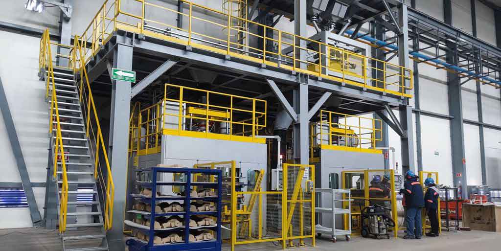
During welding, each layer was limited to a thickness of no more than 5 mm and a width of no more than 16 mm, with careful attention to sidewall fusion to avoid lack of fusion defects. The use of weaving techniques was controlled, with brief pauses at the groove edges to ensure proper melting. Slag and spatter were removed after each pass, but pneumatic tools were avoided to prevent mechanical shock to the steel casting HAZ. The welding sequence was designed to minimize distortion, with continuous welding preferred to reduce start-stop points that could introduce stress concentrations.
Following welding, the test plates underwent non-destructive testing (NDT), including ultrasonic testing (UT) and magnetic particle testing (MT), both of which indicated defect-free joints. Then, comprehensive mechanical tests were conducted to evaluate the weld joint performance. Transverse tensile tests showed that the fracture occurred in the F36 steel side, with tensile strengths of 561 MPa for horizontal welds and 559 MPa for vertical-up welds, exceeding the base metal requirements. All-weld-metal tensile tests yielded strengths of 626 MPa and 617 MPa, respectively, demonstrating the adequacy of the weld metal. Bend tests with a 40 mm diameter mandrel and 180° angle revealed no cracks or discontinuities, confirming ductility.
Charpy V-notch impact tests were performed at -40°C for the weld metal and steel casting HAZ, and at -60°C for the F36 steel HAZ. The results, summarized in Table 4, indicated excellent toughness, with average impact energies above 90 J for all locations. This is particularly noteworthy for the steel casting HAZ, where coarse grains can often lead to brittleness; the controlled thermal cycle evidently preserved toughness.
| Test Location | Charpy Impact Energy at -40°C (J) | Charpy Impact Energy at -60°C (J) |
|---|---|---|
| Weld Center (Surface) | 95 | — |
| Weld Fusion Line (Surface) | 102 | — |
| Steel Casting HAZ +2mm | 98 | — |
| F36 Steel HAZ +2mm | — | 105 |
| Weld Center (Mid-thickness) | 92 | — |
| Steel Casting HAZ (Mid-thickness) | 96 | — |
Table 4: Charpy impact test results for the welded joint (average values).
Macro-examination of the weld cross-sections revealed no defects such as cracks or lack of fusion, confirming the soundness of the welding procedure for steel casting. Vickers hardness tests were conducted at various locations, including near the top surface, root, and bottom surface. The hardness values, as shown in Table 5, were within acceptable limits, with the steel casting HAZ showing slight hardening (up to 272 HV10) but no excessive values that would indicate martensitic transformation or embrittlement.
| Location | Steel Casting Base Metal (HV10) | Steel Casting HAZ (HV10) | Weld Center (HV10) | F36 Steel HAZ (HV10) | F36 Steel Base Metal (HV10) |
|---|---|---|---|---|---|
| Near Top Surface | 190 | 272 | 210 | 261 | 183 |
| Weld Root | 206 | 258 | 230 | 228 | 185 |
| Near Bottom Surface | 204 | 252 | 218 | 242 | 179 |
Table 5: Vickers hardness test results across the welded joint.
The crack tip opening displacement (CTOD) test was conducted on full-thickness specimens extracted from the vertical-up weld, which had the highest heat input. Three specimens were tested at -10°C, with CTOD values of 0.740 mm, 0.872 mm, and 0.754 mm, all well above the required 0.25 mm. This indicates high fracture toughness and resistance to crack propagation, which is crucial for the dynamic loading conditions in offshore environments. The CTOD value can be related to the stress intensity factor K through the formula:
$$δ = \frac{K^2}{σ_y E}$$
where δ is the CTOD, K is the stress intensity factor, σy is the yield strength, and E is Young’s modulus. The high CTOD values reflect the weld’s ability to absorb energy before fracture, a key attribute for steel casting components in critical applications.
In discussion, the success of this welding procedure hinges on several factors. First, the selection of FCAW with argon-rich shielding gas reduced oxidation and improved toughness. Second, the meticulous control of preheat and interpass temperatures prevented hydrogen cracking and minimized residual stresses in the steel casting. Third, the low heat input limited grain coarsening in the HAZ, preserving mechanical properties. The use of nickel-alloyed filler metal also contributed to enhanced low-temperature performance. Compared to other studies on steel casting welding, such as those involving high-manganese cast steels or different low-alloy combinations, this approach demonstrates that with proper parameter optimization, even high-carbon-equivalent steel casting can be welded successfully to dissimilar materials.
The implications for production are significant. In the actual fabrication of the offshore component, this welding procedure was applied over 135 meters of welding, achieving a first-pass acceptance rate of 96.7%. Any defects, such as minor lack of fusion, were repaired successfully in a single rework, meeting classification society standards and owner approval. This underscores the reliability of the procedure for large-scale steel casting applications. Future work could explore automated welding techniques to further improve consistency, or investigate post-weld heat treatment options for even greater toughness enhancement in steel casting welds.
In conclusion, this research provides a comprehensive welding methodology for joining thick-section Gr420E steel casting to F36 low-alloy steel. Through rigorous testing and parameter control, the procedure ensures joint integrity with high strength, toughness, and fracture resistance. The key takeaways include the importance of preheating, interpass temperature management, and heat input limitation for steel casting welds. By adhering to these principles, manufacturers can achieve high-quality dissimilar metal joints that meet the demanding requirements of modern offshore structures. The integration of advanced testing methods like CTOD further validates the procedure’s robustness, offering a model for similar applications in heavy industry.