
In the specialized realm of manganese steel casting foundry operations, producing complex, thin-walled components like support brackets or trays represents a significant technological challenge. These castings, often employed in severe environments involving abrasive wear, impact loading, and corrosive media, demand not only exceptional mechanical properties but also geometric precision and internal soundness. Through our extensive experience in the manganese steel casting foundry sector, we have refined a comprehensive methodology for such components. This article delves into the intricate process, from initial material analysis to final heat treatment, emphasizing the practical solutions developed within our manganese steel casting foundry to prevent defects and achieve superior performance. The core of our success lies in a deep understanding of the metallurgy of high manganese steel and its interaction with innovative foundry techniques.
The material of choice for these components is typically a chromium-modified high manganese steel, commonly designated as ZGMn13Cr2. Its legendary work-hardening ability, transforming under impact to provide extreme surface hardness while retaining a tough, ductile core, makes it ideal for wear applications. However, this very characteristic poses unique challenges in the manganese steel casting foundry. The as-cast microstructure is far from optimal, consisting of austenite, brittle carbides, pearlite, and potentially harmful phosphide eutectics. The primary goal of the entire foundry and heat treatment process is to dissolve these carbides into solid solution to obtain a homogeneous, single-phase austenitic structure. The chemical composition window is critical. We meticulously control the ranges as follows:
| Element | Weight Percentage (w%) |
|---|---|
| Carbon (C) | 0.9 – 1.3 |
| Manganese (Mn) | 11.0 – 14.0 |
| Silicon (Si) | 0.3 – 0.7 |
| Chromium (Cr) | 1.5 – 2.5 |
| Phosphorus (P) | ≤ 0.07 |
| Sulfur (S) | ≤ 0.04 |
To mitigate brittleness, we often aim for the lower carbon range (0.9-1.1%) and strive for phosphorus levels as low as technologically and economically feasible. The target mechanical properties after heat treatment are a tensile strength (σ_b) exceeding 735 MPa, elongation (δ_5) greater than 25%, impact toughness (a_k) above 147 J/cm², and a hardness below 220 HB. Achieving these properties consistently is the hallmark of a proficient manganese steel casting foundry.
The component in focus, a caterpillar tray or support bracket, is a quintessential example of a complex thin-wall casting. With a finished casting weight of approximately 660 kg, it features numerous ribs, thin sections (25-45 mm), and pronounced thermal junctions at the intersections of bearing bosses and connecting plates. In service, dozens of these units are linked to form a continuous conveying system, requiring exceptional dimensional accuracy to ensure smooth, wobble-free operation under heavy and erratic loads. This structural complexity immediately dictates key considerations for any manganese steel casting foundry: methoding for controlled solidification, ensuring mold and core collapsibility to avoid hot tearing, and designing a gating system that fills the mold rapidly without excessive turbulence or temperature loss.
Our first principle in the manganese steel casting foundry is a rigorous analysis of castability. The high manganese steel’s high coefficient of thermal expansion and substantial solidification shrinkage make it highly susceptible to cracking if restrained during cooling. Furthermore, excessive pouring temperature coarsens the as-cast grain structure, increases carbide precipitation, and exacerbates microsegregation of manganese and carbon, all detrimental to final properties. Therefore, every aspect of the process must be geared towards minimizing stress generation and promoting a favorable as-cast structure. For the tray, the numerous internal cores required to form the cavities and ribs are a primary source of potential restraint. We address this by constructing composite cores with excellent collapsibility. The facing sand is a standard molding sand, but the backing is a highly permeable, low-strength mixture based on limestone sand, which readily breaks down when the metal contracts. Core prints and reinforcements are designed to allow movement, often incorporating materials like coke or rope at the center to further enhance yield and venting.
The definitive step in our manganese steel casting foundry protocol is the establishment of a robust casting process layout. We employ a two-part mold (cope and drag) with the majority of the cavity and all complex cores located in the drag. This positioning enhances stability, minimizes the risk of mold shift, and simplifies core setting. The flat mounting surface of the tray faces upward, facilitating the placement of feeder heads. Critical process parameters include a linear shrinkage allowance of 2.5%, a mold joint allowance of 2 mm, and core print allowances of 1.5 mm. Machining allowances for bearing surfaces are set at 3 mm per side to accommodate subsequent work-hardening during cutting operations.
The heart of feeding design in a manganese steel casting foundry involves identifying thermal centers and applying appropriate chilling or feeding techniques. For the tray, six major thermal junctions were identified. The three upper junctions, located on the single and double boss features, are accessible for feeding. Using the modulus method, we calculate the required feeder size. The modulus (M) is a geometric parameter defined as the volume (V) to cooling surface area (A) ratio: $$ M = \frac{V}{A} $$. For a cylindrical boss, a simplified approximation of the modulus is the diameter divided by 4 for a side-fed cylinder, but more precise calculations consider the actual geometry and feeding path. For the single boss with a thermal neck diameter of 56 mm, the casting modulus M_c was calculated as 2.8 cm. A feeder must have a larger modulus to remain liquid longer. We selected a 160x240x210 mm elliptical insulating feeder sleeve with a modulus M_f of approximately 3.43 cm. The feed metal requirement was about 45 kg. To facilitate removal and prevent adverse thermal effects during cutting, we employ washburn cores (breaker cores) made from a refractory mix, with a modulus of 3.0 cm, placed at the feeder neck. Similarly, for the two double bosses (thermal neck ~80 mm, M_c ≈ 2.75 cm), we used two 180×215 mm feeders (M_f ≈ 3.2 cm, total feed metal ~70 kg). The three lower thermal junctions, lacking direct feeding paths, are controlled using external chills to promote directional solidification towards the upper feeders. The total feeder weight of 115 kg represents a feed metal yield (casting weight / (casting weight + feeder weight)) of approximately 85%, which is efficient for a complex steel casting in a manganese steel casting foundry.
The gating system design is paramount for achieving sound castings in a manganese steel casting foundry. We utilize a bottom-gating system via a trumpet-basin runner to ensure calm, non-turbulent filling. The key design parameter is the mold filling time, which must be fast enough to prevent mistuns but controlled to minimize erosion. We base this on a desired metal rise velocity (V_L) in the mold cavity. For thin-section steel castings, a rise velocity of 15-25 mm/s is typical. For our tray with a total cavity height (H) of 330 mm, we selected V_L = 20 mm/s. The filling time (t) is therefore: $$ t = \frac{H}{V_L} = \frac{330 \text{ mm}}{20 \text{ mm/s}} = 16.5 \text{ s} $$. With a casting weight (G) of 660 kg, the required pouring rate (Q) is: $$ Q = \frac{G}{t} = \frac{660 \text{ kg}}{16.5 \text{ s}} \approx 40 \text{ kg/s} $$. Our ladle is equipped with a 45 mm diameter nozzle, which at a typical head height provides a discharge rate (Q_nozzle) of about 42 kg/s. We then design an open gating system (ΣA_sprue > ΣA_runner > ΣA_gates) to maintain a non-pressurized flow and minimize aspiration. The area ratios are established as: $$ A_{\text{nozzle}} : A_{\text{sprue}} : A_{\text{runner}} : A_{\text{gates}} = 1 : 1.9 : 1.9 : 2.2 $$. Given A_nozzle = π*(45/2)^2 ≈ 1590 mm² (15.9 cm²), we determine:
A_sprue ≈ 30.2 cm² (using a 60 mm diameter sprue),
A_runner ≈ 30.2 cm² (rectangular section, total 16 cm² per side, symmetrically arranged),
A_gates ≈ 35 cm² total, split into an upper level (4 gates, each ~9 cm²) and a bottom level using the sprue extensions as direct gates. This configuration ensures the calculated pour rate is achieved while promoting smooth filling from the bottom up, a standard best practice in any advanced manganese steel casting foundry.
Pouring temperature is a critical lever for quality control in the manganese steel casting foundry. Too high a temperature increases gas solubility, shrinkage porosity, and grain size. Too low a temperature risks mistuns and cold shuts. Based on extensive trials, we establish a pouring temperature range of 1410°C to 1430°C. To account for heat loss during transfer, the ladle is tapped from the furnace at 1480-1520°C, and temperature is finely adjusted through argon stirring and controlled holding before pouring commences.
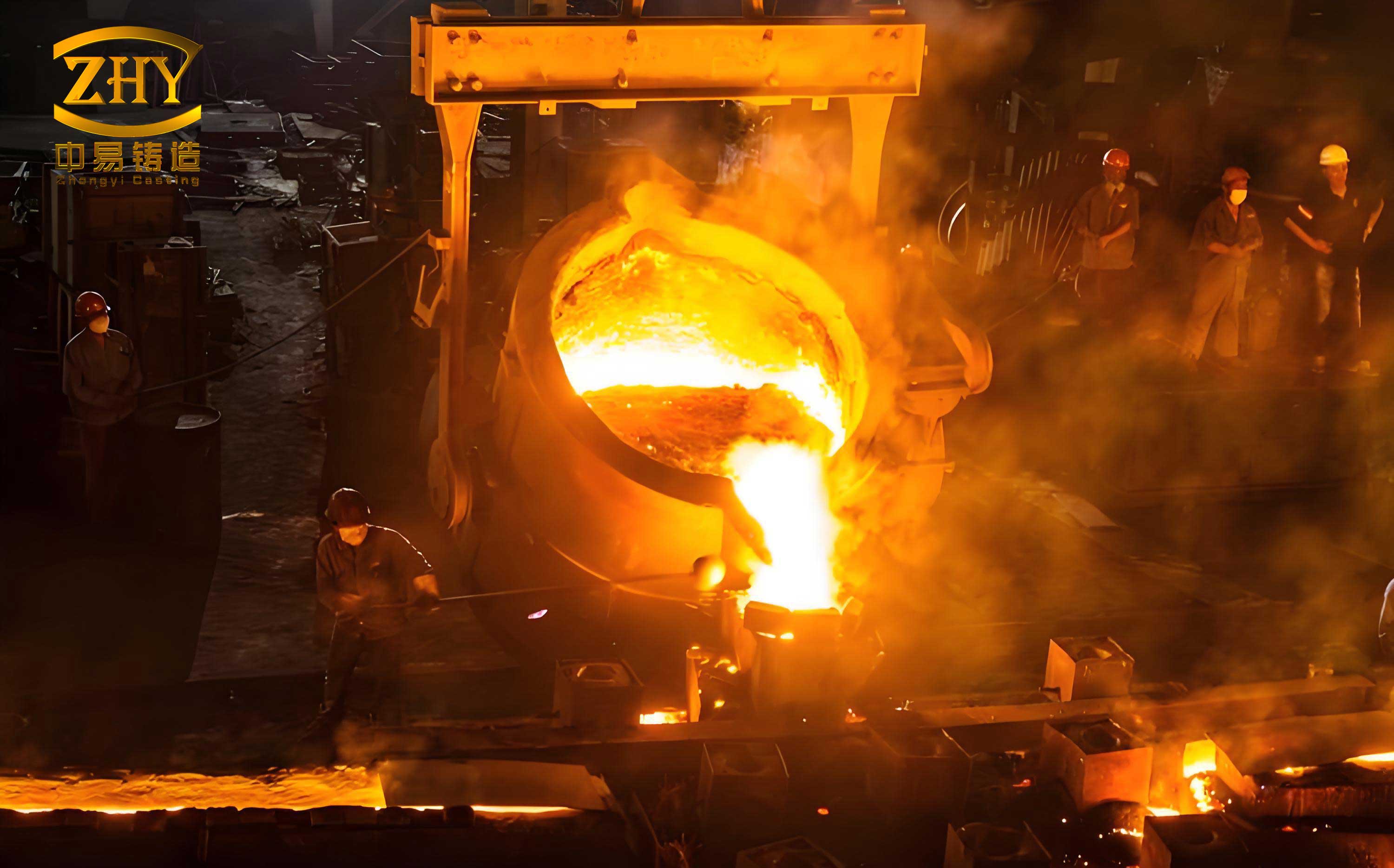
The melting practice in our manganese steel casting foundry is conducted in a basic electric arc furnace using an oxidizing process, typically a three-phase operation: melt-down, oxidizing, and reducing. The melt-down phase is accelerated by oxygen lancing to reduce time and energy consumption. The oxidizing phase is crucial for impurity removal. We initiate a vigorous carbon boil by having a melt carbon content of 3-6% and then oxidizing down to below 0.15% C. This boil effectively removes hydrogen and nitrogen and helps float out non-metallic inclusions. Equally important is phosphorus removal during this stage under an oxidizing, fluid slag with a basicity (CaO/SiO₂) above 2.5. We aim to reduce phosphorus to below 0.020% before slagging off. The reducing phase involves deoxidation and alloying adjustment under a reducing atmosphere, first with a calcium carbide slag and finally a white slag. Ferromanganese and ferrochromium are added, with careful selection of low-phosphorus grades to keep the final P content within specification. After final adjustments, the steel is tapped into a ladle for argon stirring refinement, which homogenizes temperature and composition and promotes further inclusion flotation.
Heat treatment, known as water quenching or toughening, is what unlocks the legendary properties of manganese steel and is a non-negotiable final step in the manganese steel casting foundry process chain. The objective is to heat the casting to a temperature where all carbides are dissolved into the austenite (typically 1050-1100°C), hold for sufficient time to achieve homogeneity, and then quench it rapidly in water to retain the carbon in super-saturated solid solution, preventing reprecipitation of carbides. Our specific cycle is as follows: Castings are loaded into a furnace at a temperature below 300°C to avoid thermal shock. They are soaked for 1-1.5 hours, then heated slowly (<70°C/h) to 650-670°C to relieve residual casting stresses. After a 2-hour hold at this intermediate temperature, the furnace is ramped as quickly as possible to the final solutionizing temperature of 1100-1150°C. The holding time is critical and is determined by the section thickness; for our tray, 4-5 hours is standard. The most critical operation is the transfer from furnace to quench tank. We strive to complete this in 20-30 seconds, ensuring the casting enters the water at a temperature not below 950°C. The quench water must be agitated and copious—typically 8-10 times the weight of the charge—to prevent steam blanketing and ensure a rapid, uniform quench. The initial water temperature is kept below 35°C and the final temperature after quenching below 50°C.
Operational expertise in the manganese steel casting foundry is what bridges theory and sound castings. Key measures to prevent cracking include strict control of shakeout and riser removal. We loosen the molding flasks approximately 30 minutes after pouring to reduce restraint, but complete shakeout is delayed for a minimum of 24 hours to allow the casting to cool in a more stress-relieved state. Risers are removed using oxygen-cutting torches only after the casting has been water-quenched, as the austenitic structure is much less crack-sensitive at that stage. To enhance mechanical properties, beyond strict control of chemistry and heat treatment, we focus on melt cleanliness. The final argon stirring and a brief holding period after stirring allow inclusions to rise to the slag. The controlled, relatively low pouring temperature also refines the as-cast grain structure, providing a better starting point for the solutionizing heat treatment.
The results from implementing this comprehensive approach in our manganese steel casting foundry have been highly successful. Over multiple production campaigns, yielding several hundred castings, the mechanical property pass rate has been 100%, with all values exceeding the specified minimums. Non-destructive testing (radiography and dye penetrant) has shown a very low incidence of shrinkage or hot tear defects, leading to a overall casting yield above 98%. Most importantly, the first set of trays produced using this methodology has performed flawlessly in the field for over three years under severe abrasive and corrosive conditions, validating the robustness of our manganese steel casting foundry processes. This success underscores the importance of an integrated view that considers material science, foundry engineering, and metallurgical heat treatment as inseparable parts of a single manufacturing discipline dedicated to high-performance manganese steel components.
In conclusion, the production of complex, thin-walled high manganese steel castings demands a holistic and meticulously controlled approach at every stage of the manganese steel casting foundry operation. From the initial design of collapsible cores and modulus-based feeding systems to the precise control of melting, pouring, and the critical water-quenching heat treatment, each step is interlinked. The repeated emphasis on the manganese steel casting foundry process highlights its system-wide importance. The formulas and principles discussed, such as $$ t = \frac{H}{V_L} $$ for filling time and $$ M = \frac{V}{A} $$ for modulus calculations, are not mere academic exercises but essential tools for daily decision-making on the foundry floor. By adhering to these principles and continuously refining our practices, we ensure that the unique advantages of manganese steel are fully realized in the most challenging applications, solidifying the reputation of a modern manganese steel casting foundry as a center of manufacturing excellence.