
In my extensive experience within the manganese steel casting foundry industry, the pursuit of enhanced durability and performance for critical wear components is a constant driver. One significant project involved the production of ZGMn13 crusher rollers, where traditional sand casting methods yielded components with inherent shortcomings like internal porosity and suboptimal wear resistance, leading to premature failure. After thorough analysis, my team and I championed the transition to a metal mold casting process. This shift was not merely a change in tooling; it represented a fundamental re-engineering of the manganese steel casting foundry approach for this specific part, leveraging the rapid cooling and superior heat extraction of metal molds to refine the microstructure. The outcome was a remarkable improvement, extending service life by a factor of 1.5. This article details the comprehensive methodology, from initial feasibility assessment to precise process control, that defines a successful manganese steel casting foundry operation using permanent molds.
The core challenge was a roller with dimensions of approximately 610 mm in diameter and 305 mm in length, with a nominal wall thickness of 70-75 mm. The cylindrical external geometry presented an ideal candidate for metal mold casting, as it allowed for straightforward mold parting and extraction without hindering solidification shrinkage. However, the internal cavity necessitated the continued use of a sand core. The annual demand of around 150 pieces provided the economic justification for investing in reusable metal tooling, a key consideration for any manganese steel casting foundry looking to optimize batch production. The primary goal was to achieve a denser, more homogeneous austenitic matrix in the high manganese steel, thereby unlocking its full work-hardening potential upon impact and abrasion in service.
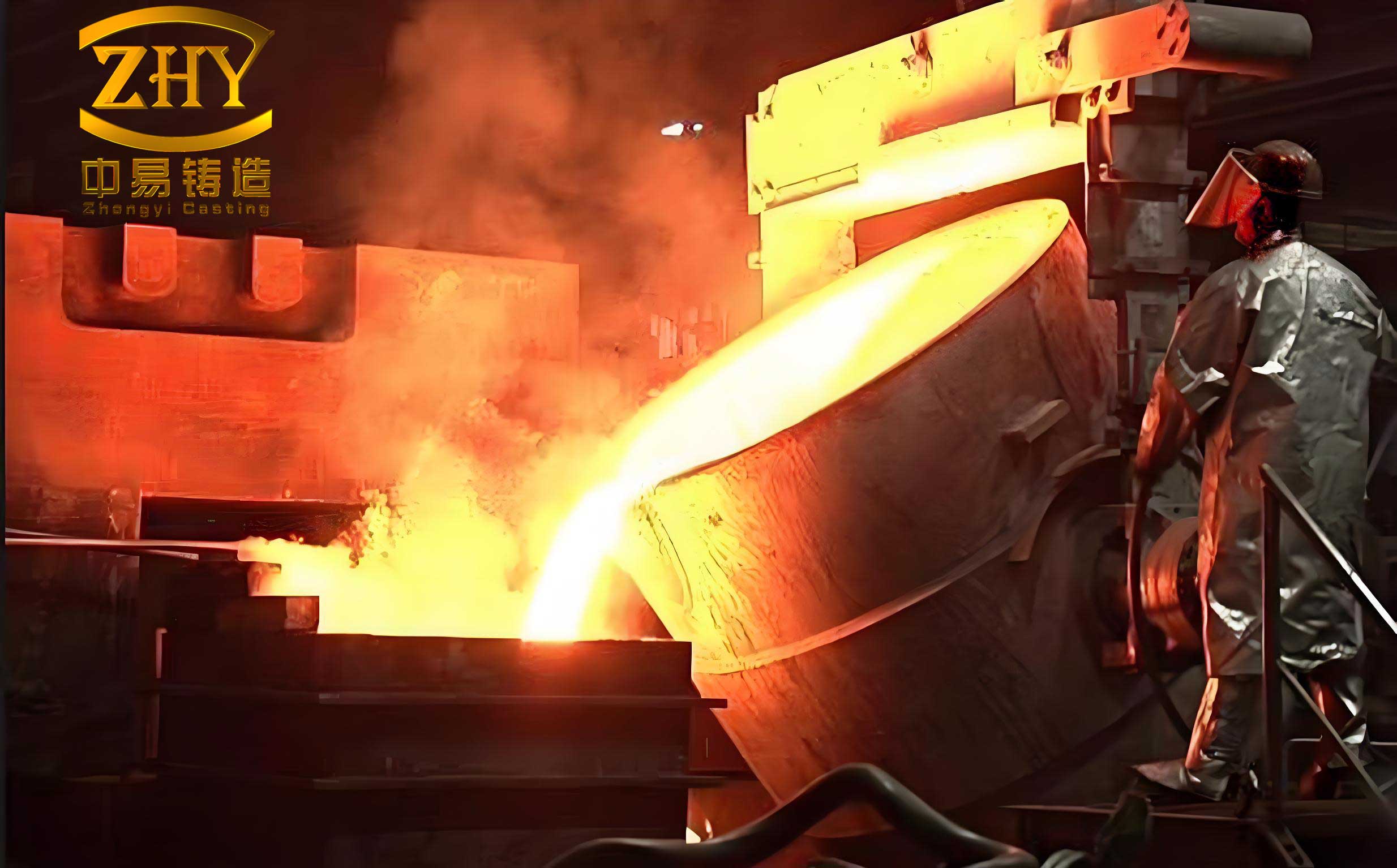
The initial feasibility study was paramount. We evaluated the part geometry and production volume against the capabilities of our manganese steel casting foundry. The relatively uniform wall thickness was a favorable factor, mitigating risks of thermal stress-induced cracking or isolated shrinkage cavities that can plague more irregular shapes in metal molds. A summary of the feasibility criteria is presented below.
| Evaluation Criterion | Assessment for Metal Mold Casting | Rationale |
|---|---|---|
| Production Batch Size | Suitable (~150 units/year) | Justifies initial mold cost and setup time. |
| External Geometry | Excellent (Cylindrical) | Facilitates easy mold parting and casting ejection. |
| Wall Thickness Uniformity | Good (70-75 mm) | Promotes uniform cooling, reducing stress and porosity. |
| Internal Geometry | Requires Sand Core | Metal core would impede contraction; sand core remains necessary. |
| Alloy Fluidity | Challenging but manageable | High Mn steel has lower fluidity than cast iron; requires careful gating and higher pouring temperature. |
With feasibility established, the heart of the process—the casting工艺 design—commenced. We adopted a vertical pouring position. This orientation ensures stable mold filling, promotes favorable temperature gradients for directional solidification toward the risers, and allows for secure placement and venting of the sand core. A horizontal parting plane was selected, effectively dividing the mold into upper and lower halves. This design simplifies mold assembly, core setting, and the integration of the feeding system.
The gating system is the lifeline of any casting. For this manganese steel casting foundry application, a bottom-gating system was chosen to minimize turbulence and air entrapment during the fill. To determine the correct dimensions, we started with the ladle nozzle as the choke point. Using a ladle with a nozzle diameter (d) of 45 mm, the cross-sectional area is calculated as:
$$F_{nozzle} = \frac{\pi d^2}{4} = \frac{\pi \times (45)^2}{4} \approx 1590 \text{ mm}^2$$
For an open, pressurized system common in steel foundries, the area ratios were designed according to established principles for manganese steel casting foundry practice:
$$F_{nozzle} : F_{sprue} : F_{runner} : F_{ingate} = 1 : (1.8 \sim 2.0) : (1.8 \sim 2.0) : 2.0$$
Based on this ratio and standard refractory tube sizes, the following dimensions were implemented:
| Gating Element | Design Specification | Cross-Sectional Area (mm²) |
|---|---|---|
| Sprue | Ø60 mm refractory tube | ~2827 |
| Runner (2 channels) | Tapered: 48/40 mm top/bottom width, 36 mm height | ~1584 per channel |
| Ingate (2 channels) | Tapered: 48/40 mm top/bottom width, 36 mm height | ~1584 per channel |
To validate this design, we calculated the actual pouring time ($\tau_{actual}$) and the metal rise velocity in the mold cavity ($V_{rise}$). The mass of poured metal (G) is approximately 490 kg, and the mass flow rate ($V_G$) for a 45 mm nozzle is about 42 kg/s.
$$\tau_{actual} = \frac{G}{V_G} = \frac{490}{42} \approx 11.7 \text{ seconds}$$
The height of the mold cavity (C), including machining allowance, is 323 mm.
$$V_{rise} = \frac{C}{\tau_{actual}} = \frac{323}{11.7} \approx 27.6 \text{ mm/s}$$
This rise velocity exceeds the minimum recommended velocity of 25 mm/s for steel castings, confirming the gating design prevents mistrust and cold shuts, a critical check in manganese steel casting foundry operations.
Feeding design is equally crucial. The risers, placed in the sand upper mold section, were designed using the modulus method. First, the casting modulus ($M_c$) at the hot spot (the cylindrical wall) was calculated, where a = height (323 mm) and b = thickness (75 mm).
$$M_c = \frac{a \times b}{2(a + b)} = \frac{323 \times 75}{2(323 + 75)} \approx 30.4 \text{ mm} = 3.04 \text{ cm}$$
For an insulated riser, the riser modulus ($M_r$) should satisfy $M_r \ge 1.2 M_c$. We designed risers with a modulus of approximately 3.04 cm. The volumetric shrinkage ($\epsilon$) for ZGMn13 at a pouring temperature of around 1480°C is approximately 5.5%. Using an insulated cylindrical riser with a diameter-to-height ratio optimized for feeding efficiency ($\eta \approx 25\%$), the required riser volume ($V_r$) to compensate for shrinkage in the casting volume ($V_c \approx 4.87 \times 10^7 \text{ mm}^3$) can be derived from:
$$V_c \le \frac{\eta – \epsilon}{\epsilon} \times V_r$$
Rearranging to solve for the minimum $V_r$:
$$V_r \ge \frac{\epsilon \times V_c}{\eta – \epsilon} \approx \frac{0.055 \times 4.87 \times 10^7}{0.25 – 0.055} \approx 1.37 \times 10^7 \text{ mm}^3$$
We selected three oval-shaped insulated risers with dimensions 140 mm x 210 mm x 185 mm each, providing a total volume well above this requirement. The number of risers (N) was verified using the concept of riser contact perimeter, where D is the casting diameter (540 mm) and ψ is the riser contact length factor (0.38).
$$N = \frac{\pi D \psi}{L_r} = \frac{\pi \times 540 \times 0.38}{210} \approx 3.07 \Rightarrow 3 \text{ risers}$$
This riser configuration ensured sound, shrinkage-free castings from our manganese steel casting foundry.
The metal mold itself was a cornerstone of this project. We designed a horizontally parted mold made from Grade HT200 gray iron, a material with good thermal conductivity, machinability, and cost-effectiveness for the demands of a manganese steel casting foundry. The mold wall thickness was set at 70 mm—a balance between sufficient thermal mass to stabilize the process and avoid excessive weight. A critical aspect was managing the thermal cycle of the mold. Before each pour, the mold was preheated to a temperature between 150°C and 250°C using a mobile furnace. This preheating is non-negotiable in a manganese steel casting foundry using metal molds; it prevents thermal shock to the mold, reduces chilling of the metal to avoid mistrust, and eliminates moisture-related gas defects. The preheating parameters are summarized below:
| Process Parameter | Value or Range | Purpose |
|---|---|---|
| Mold Material | HT200 Gray Iron | Adequate thermal conductivity, durability, and cost. |
| Mold Wall Thickness | 70 mm | Optimizes cooling rate and mold structural integrity. |
| Mold Preheating Temperature | 150°C – 250°C | Prevents thermal shock, reduces chilling, eliminates moisture. |
| Preheating Time | 15-20 minutes (longer in winter) | Ensures uniform temperature attainment. |
Pouring practice required careful adjustment. The high thermal conductivity of the metal mold meant that the pouring temperature for this manganese steel casting foundry process had to be towards the upper end of the standard range for ZGMn13, typically around 1480-1520°C. To achieve this consistently, we scheduled these castings to be poured within the first few molds after tapping the furnace. The pouring sequence was controlled: slow initially to avoid splash and turbulence, then rapid to ensure complete filling, and finally slow again at the end to top off the risers properly. This level of control is emblematic of advanced practices in a modern manganese steel casting foundry.
After pouring, the control of solidification and ejection is vital. The cylindrical shape of the roller aided in its contraction away from the mold walls. We did not enforce an excessively strict shakeout time; instead, we allowed the casting to cool in the mold until it reached a temperature where handling was safe and dimensional stability was achieved, typically aligning with the cooling time of other similar complexity castings from the same heat. The interval between ejection and the next mold assembly was sufficient for the mold to cool back to near its preheating temperature, creating a sustainable thermal cycle. The relationship between cooling time ($t$), casting modulus ($M_c$), and the temperature differential ($\Delta T$) can be conceptually described by Chvorinov’s rule, adapted for metal mold conditions:
$$t = B \cdot \left( \frac{V_c}{A_c} \right)^n = B \cdot (M_c)^n$$
Where $B$ and $n$ are constants dependent on the mold material and casting alloy—parameters meticulously refined through experience in our manganese steel casting foundry.
The success of this metal mold casting process was quantitatively and qualitatively evident. Over a production run of hundreds of rollers, the yield of sound castings consistently exceeded 98%. Metallographic examination revealed a significantly denser austenitic matrix with fewer micro-shrinkages and non-metallic inclusions compared to sand-cast counterparts. This microstructural refinement directly translated to superior in-service performance. Field reports confirmed that the wear life of these metal mold-cast rollers increased by an average of 150% compared to the traditional sand-cast versions. Furthermore, the manganese steel casting foundry benefited from operational efficiencies: a reduction of over 40% in consumed molding sand, decreased cleaning and fettling labor due to superior surface finish, and higher throughput from the reusable molds.
To further generalize the principles, let’s consider the key metallurgical and thermal equations governing high manganese steel solidification in a metal mold. The heat flux ($q$) from the casting to the mold is critical and can be approximated by:
$$q = h \cdot \Delta T$$
where $h$ is the interfacial heat transfer coefficient and $\Delta T$ is the temperature difference. For a manganese steel casting foundry using iron molds, $h$ is relatively high, promoting rapid solidification. The secondary dendrite arm spacing (SDAS), a key indicator of microstructural fineness, is inversely related to the local solidification time or cooling rate ($\dot{T}$):
$$\text{SDAS} = k \cdot (\dot{T})^{-n}$$
where $k$ and $n$ are material constants. The rapid cooling in a metal mold reduces SDAS, leading to improved tensile and impact properties. This scientific underpinning validates the empirical success observed in our manganese steel casting foundry project.
In conclusion, the implementation of metal mold casting for high manganese steel rollers represents a paradigm shift in production methodology for demanding wear parts. The process demands a holistic integration of design, thermal management, and precise control—all hallmarks of a sophisticated manganese steel casting foundry. From the initial feasibility analysis and meticulous gating/risering calculations to the disciplined preheating and pouring protocols, every step contributes to the final goal: a component with exceptional integrity and longevity. The tables and formulas presented here serve as a blueprint, but their successful application relies on the deep process knowledge inherent to a skilled manganese steel casting foundry team. The transition from sand to metal mold is not just about changing a tool; it’s about embracing a system that maximizes the inherent potential of high manganese steel, delivering value through extended service life and manufacturing efficiency. This case study underscores that in the competitive landscape of foundry work, innovation in processes like metal mold casting is essential for the manganese steel casting foundry to meet evolving industrial challenges.