
As a foundry engineer specializing in heavy industrial castings, I have dedicated significant effort to improving the quality of large and complex casting parts, particularly those used in marine diesel engines. The cylinder block, a critical casting part in two-stroke diesel engines, presents formidable challenges due to its massive size, thick sections, and stringent material requirements. In this article, I will share my comprehensive analysis and proven solutions for the defects commonly encountered in such casting parts, focusing on a specific cylinder block casting part weighing 40.5 tons with wall thicknesses of 60–80 mm, made of HT250 gray iron. The goal is to provide a detailed, first-person account of how systematic process optimization can dramatically enhance the integrity and reliability of these essential casting parts.
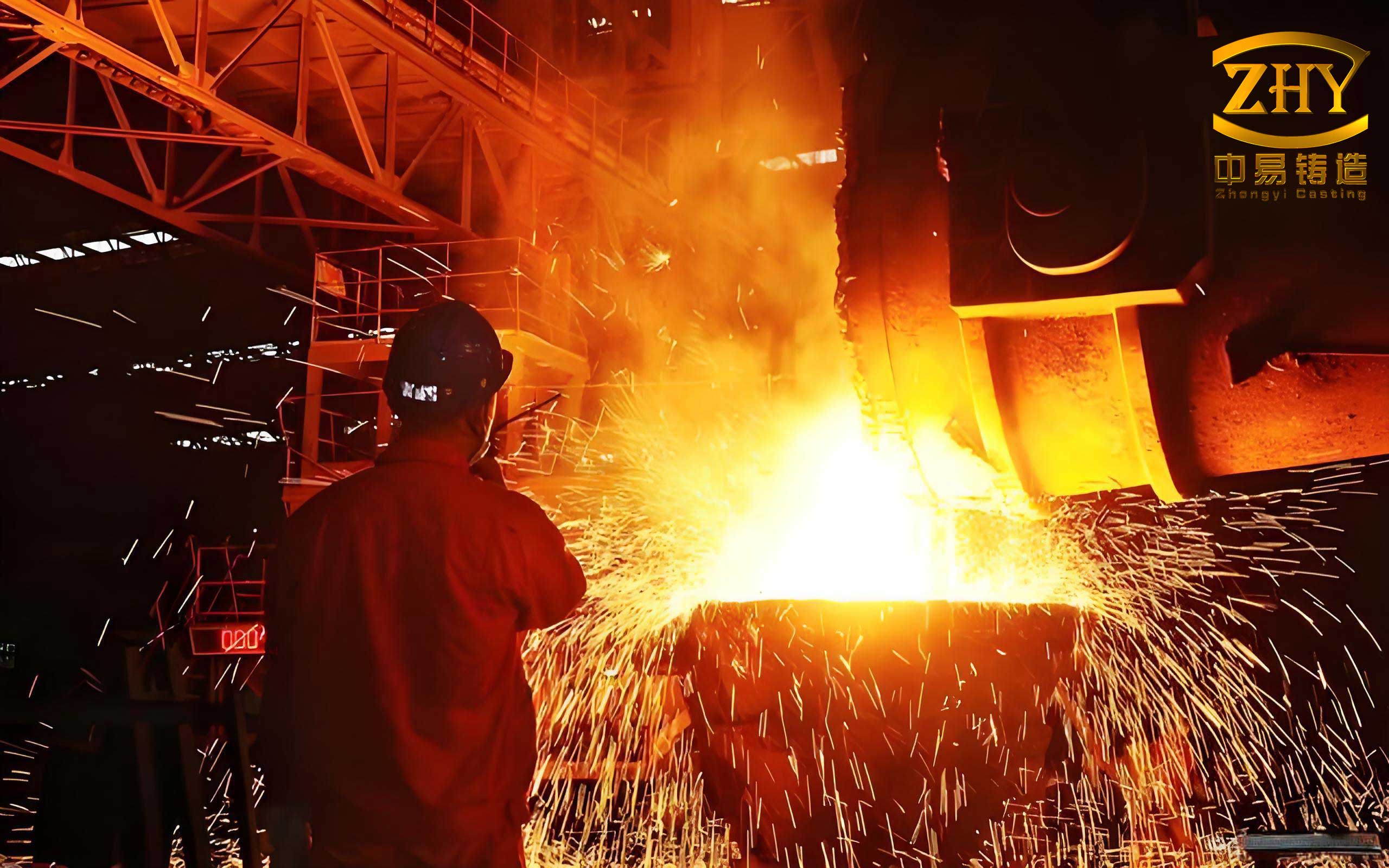
This image illustrates the intricate geometry and substantial dimensions of the cylinder block casting part, highlighting the thick sections that are prone to defects during solidification. Producing such a casting part requires meticulous attention to every aspect of the foundry process, from mold design to melt treatment.
Introduction to the Casting Part and Its Challenges
The casting part under discussion is a cylinder block for a WCH two-stroke marine diesel engine. It has an overall envelope of approximately 4100 mm × 2065 mm × 2170 mm, with a main bore diameter of 860 mm and a bore center distance of 1292 mm. The specified material is HT250 gray iron, which must exhibit a flake graphite structure with Type A graphite, a graphite grade of 4, and a pearlite content exceeding 95%. The tensile strength on the casting part本体 must be at least 190 MPa, and the production process avoids stress-relief annealing to save time and cost. This casting part is典型 of thick-section components where the solidification dynamics are complex, leading to common defects like shrinkage porosity, slag inclusions, and blowholes. Each defect can compromise the performance of the casting part, necessitating rigorous analysis and corrective actions.
Initial Casting Process for the Cylinder Block Casting Part
The original manufacturing process for this casting part employed a bottom-gating system with an open design. The gating system comprised two vertical sprues, each with a diameter of 100 mm, 34 ingates of 40 mm diameter, and trapezoidal horizontal runners equipped with ceramic filters to trap inclusions. A semi-quantitative pouring cup was used, along with six insulating top risers positioned at critical locations such as bore faces and thick sections. Chills made of HT200, with thicknesses ranging from 60 to 80 mm, were placed at strategic hot spots like the bore faces and filler函孔 areas. Venting was achieved through core vents in bolt hole cores and mold cavity vents on the top surfaces of ribs and other non-thick regions.
The melting practice involved a charge mix of 20 wt.% pig iron, 60 wt.% high-quality scrap steel, and 20 wt.% returns. The initial chemical composition range for the casting part is summarized in Table 1.
| Element | Range |
|---|---|
| Carbon (C) | 3.0–3.1 |
| Silicon (Si) | 1.3–1.4 |
| Manganese (Mn) | 0.8–0.9 |
| Phosphorus (P) | < 0.1 |
| Sulfur (S) | 0.06–0.09 |
| Copper (Cu) | 0.6–0.7 |
The molten iron was held at 1500–1520°C for 5–10 minutes before tapping, with inoculation performed in the ladle. The pouring temperature was maintained at 1320–1340°C, with a filling time of 210–240 seconds, and the total time from inoculation to complete pouring was kept under 25 minutes. Despite these controls, the casting part consistently exhibited defects, prompting a detailed investigation and optimization.
Theoretical Framework for Defect Formation in Thick-Section Casting Parts
Understanding the underlying principles of solidification and gas evolution is crucial for addressing defects in casting parts. For thick-section casting parts like this cylinder block, the solidification time is prolonged, which can be estimated using Chvorinov’s rule:
$$ t_s = B \left( \frac{V}{A} \right)^n $$
where \( t_s \) is the solidification time, \( V \) is the volume of the casting part, \( A \) is its surface area, \( B \) is a constant dependent on mold material and pouring conditions, and \( n \) is an exponent typically around 2. A high modulus \( V/A \), characteristic of thick sections, leads to longer \( t_s \), increasing the risk of shrinkage and gas-related defects.
The volume change during solidification, which contributes to shrinkage, can be expressed as:
$$ \Delta V = V_l \cdot \alpha_l \cdot \Delta T_l + V_s \cdot \alpha_s \cdot \Delta T_s $$
where \( V_l \) and \( V_s \) are the volumes of the liquid and solid phases, \( \alpha_l \) and \( \alpha_s \) are their respective coefficients of thermal expansion, and \( \Delta T_l \) and \( \Delta T_s \) are the temperature changes. In gray iron, graphitization expansion can partially compensate for this shrinkage, but in thick sections, the compensation may be insufficient.
Gas solubility in molten iron, relevant for blowhole formation, follows Sieverts’ law:
$$ S_g = k \sqrt{P_g} $$
where \( S_g \) is the solubility, \( k \) is a temperature-dependent constant, and \( P_g \) is the partial pressure of the gas. During cooling, dissolved gases may precipitate, forming bubbles that become trapped in the casting part.
Shrinkage Porosity in the Casting Part: Analysis and Solutions
Shrinkage porosity was a prevalent defect in this cylinder block casting part, manifesting primarily at the top of the filler函孔 near riser roots, with dimensions around 105 mm × 60 mm. This location is a thermal hotspot where solidification is slower, leading to inadequate feeding if the riser system is not optimally designed.
The root causes of shrinkage in this casting part included a relatively low carbon content, which reduced fluidity and graphitization potential, and a high pouring temperature that increased the total heat content and thermal gradient. To address these issues, I implemented several modifications. First, the pouring temperature was lowered to 1300–1320°C to reduce the thermal gradient and promote directional solidification. Second, the carbon content was increased to 3.1–3.2 wt.% to enhance fluidity and graphitization, as higher carbon equivalent (CE) promotes better feeding. The CE is calculated as:
$$ CE = C + \frac{Si + P}{3} $$
With the optimized composition, the CE increased from approximately 3.43–3.53 wt.% to 3.53–3.63 wt.%, favoring reduced shrinkage tendency. Third, the riser height was increased by 150 mm to improve feeding pressure, and vent sizes on the risers were reduced from Φ30 mm to Φ20 mm to maintain higher pressure within the mold cavity. These changes are summarized in Table 2.
| Parameter | Original Value | Optimized Value | Rationale |
|---|---|---|---|
| Pouring Temperature | 1320–1340°C | 1300–1320°C | Lower thermal gradient, promote directional solidification |
| Carbon Content | 3.0–3.1 wt.% | 3.1–3.2 wt.% | Increase fluidity and graphitization expansion |
| Riser Height | 250 mm (assumed) | 400 mm | Enhance feeding pressure and volume |
| Riser Vent Size | Φ30 mm | Φ20 mm | Maintain higher internal pressure for better feeding |
After these adjustments, the defect rate for shrinkage porosity in the casting part dropped significantly. In a production batch of 20 casting parts, only two exhibited minor shrinkage, which was fully removed during rough machining. The average defect area per casting part decreased from over 6000 mm² to less than 600 mm², demonstrating the effectiveness of the measures.
Slag Inclusions in the Casting Part: Analysis and Solutions
Slag inclusions appeared as irregular black patches on the surface of the casting part, often near window-like features. These defects stem from non-metallic inclusions entrained during pouring or from reactions between the molten iron and mold coatings. The probability of slag entrapment, \( P_{slag} \), can be qualitatively related to the melt viscosity \( \eta \) and pouring velocity \( v \):
$$ P_{slag} \propto \frac{\eta \cdot v}{g} $$
where \( g \) is gravitational acceleration. High viscosity and turbulent flow increase slag incorporation.
To combat slag inclusions in this casting part, I focused on improving melt cleanliness and inoculation efficiency. The molten iron was subjected to high-temperature holding at 1520–1530°C before tapping, ensuring complete dissolution of alloying elements like ferromanganese and copper. This step reduces the presence of undissolved particles that could become inclusions. Additionally, the inoculation method was changed from ladle inoculation to stream inoculation, where the inoculant is added directly during pouring, leading to better assimilation and effectiveness. A stopper head was also employed in the pouring system to minimize slag carryover from the ladle. The optimization measures are detailed in Table 3.
| Parameter | Original Practice | Optimized Practice | Effect |
|---|---|---|---|
| Holding Temperature | 1500–1520°C | 1520–1530°C | Ensures complete alloy dissolution, reduces solid inclusions |
| Inoculation Method | Ladle inoculation | Stream inoculation | Improves inoculant efficiency, promotes finer graphite |
| Pouring Technique | Open pouring | Use of stopper head | Reduces slag entrainment from ladle |
Following these changes, slag inclusion defects in the casting part were reduced by 95%, with only one out of 20 casting parts showing a minor inclusion that was easily ground away. This marked improvement underscores the importance of melt treatment and controlled pouring for high-quality casting parts.
Blowholes in the Casting Part: Analysis and Solutions
Blowholes, characterized by rounded cavities often containing traces of slag, were frequently found on the upper surfaces of the casting part after rough machining. These defects arise from gas entrapment during mold filling or from gas evolution during solidification, exacerbated by high sulfur content and inadequate venting.
To address blowholes, I revised the venting strategy by adding mold cavity vents at the four corners of the cope box and removing vents from non-thick areas like ribs. This ensures efficient gas escape from the regions where gas tends to accumulate. The mold was preheated to above 50°C using hot air blowers to eliminate moisture, which is a common source of hydrogen gas. The sulfur content in the melt was tightened to the lower end of the specification, from 0.06–0.09 wt.% to 0.06–0.07 wt.%, to minimize the formation of gas-promoting sulfides like FeS and MnS. Furthermore, high-temperature holding at 1520–1530°C was maintained to improve overall melt quality and reduce gas content. These interventions are summarized in Table 4.
| Parameter | Original Condition | Optimized Condition | Impact |
|---|---|---|---|
| Venting Design | Vents on ribs and top surfaces | Vents at four cope corners, ribs vents removed | Directed gas escape from critical areas |
| Mold Preheating | No specific preheating | Preheated to >50°C with hot air | Reduces moisture-derived gas generation |
| Sulfur Content | 0.06–0.09 wt.% | 0.06–0.07 wt.% | Lowers gas formation tendency |
| Holding Temperature | 1500–1520°C | 1520–1530°C | Enhances melt cleanliness, reduces dissolved gases |
As a result, the blowhole defect rate in the casting part plummeted from 6% to less than 0.5%, validating the effectiveness of comprehensive gas control measures. This improvement is critical for ensuring the pressure-tightness and mechanical integrity of the casting part in service.
Integrated Process Optimization and Quality Metrics for the Casting Part
The optimizations described were implemented in an integrated manner, recognizing that defects in casting parts often have interrelated causes. For instance, lowering the pouring temperature helps with shrinkage but must be balanced against fluidity requirements to avoid cold shuts. The fluidity length \( L_f \) can be estimated as:
$$ L_f = k_f \cdot \sqrt{t_f} $$
where \( k_f \) is a fluidity constant and \( t_f \) is the time available for flow before solidification. By setting the pouring temperature at 1300–1320°C, I ensured that \( L_f \) remained sufficient for complete mold filling while minimizing shrinkage risks.
To monitor the overall quality of the casting part, I employed statistical process control (SPC) for key parameters. Table 5 shows the controlled ranges after optimization.
| Parameter | Target Range | Monitoring Frequency | Standard Deviation |
|---|---|---|---|
| Pouring Temperature | 1300–1320°C | Every pour | < 5°C |
| Carbon Content | 3.1–3.2 wt.% | Per heat | < 0.03 wt.% |
| Holding Temperature | 1520–1530°C | Before tapping | < 3°C |
| Pouring Time | 200–220 seconds | Every pour | < 10 seconds |
The defect density \( D_d \), defined as the total defect area per unit surface area of the casting part, was used as a quantitative metric:
$$ D_d = \frac{\sum A_{defects}}{A_{total}} $$
where \( \sum A_{defects} \) is the sum of defect areas on a casting part and \( A_{total} \) is its total surface area. After optimization, \( D_d \) decreased by over 90%, indicating a substantial improvement in the quality of the casting part.
Material Science Considerations for the HT250 Casting Part
The HT250 grade specified for this casting part demands a careful balance of composition and microstructure. The graphite morphology directly influences mechanical properties and defect propensity. Type A graphite with a grade 4 distribution provides good thermal conductivity and machinability, which are essential for the cylinder block casting part. Inoculation plays a pivotal role in achieving this structure. The inoculant efficiency \( E_{inc} \) can be defined as the increase in graphite nodule count per unit weight of inoculant. For this casting part, using a FeSi-based inoculant with stream inoculation resulted in a finer and more uniform graphite distribution, contributing to reduced shrinkage and improved strength.
The pearlite content, required to be above 95%, is controlled through alloying with copper and careful cooling rates. The presence of pearlite enhances the hardness and wear resistance of the casting part. The relationship between cooling rate \( \dot{T} \) and pearlite formation can be expressed as:
$$ \dot{T} = \frac{dT}{dt} \propto \frac{1}{t_s} $$
where \( t_s \) is the solidification time. By using chills and controlling wall thickness, I managed the cooling rate to ensure high pearlite content without inducing excessive stresses in the casting part.
Economic and Environmental Benefits of Optimizing the Casting Part
Beyond technical improvements, the process optimizations yielded significant economic and environmental advantages. The reduction in defect rates lowered the scrap rate for the cylinder block casting part from an estimated 5% to less than 1%, resulting in substantial cost savings in materials and energy. Fewer defective casting parts mean less remelting, which reduces energy consumption and greenhouse gas emissions from the foundry.
Lowering the sulfur content not only improved the quality of the casting part but also minimized the emission of sulfur oxides during melting, contributing to cleaner air. Additionally, the enhanced durability and reliability of the casting part extend the service life of the diesel engine, reducing the frequency of replacements and the associated environmental footprint over the engine’s lifecycle.
Conclusion
Through a methodical approach combining theoretical analysis and practical adjustments, the common defects in thick-section marine diesel engine cylinder block casting parts have been effectively mitigated. Key strategies included optimizing the chemical composition to enhance fluidity and graphitization, redesigning the venting system to facilitate gas escape, implementing high-temperature holding for melt cleanliness, and refining inoculation practices. These measures collectively reduced shrinkage porosity, slag inclusions, and blowholes to minimal levels, as validated in production batches. The success of this optimization underscores the importance of a holistic understanding of foundry processes for complex casting parts. As a casting engineer, I believe that continuous improvement based on such detailed analysis is essential for producing high-integrity casting parts that meet the rigorous demands of marine applications.
Looking ahead, further advancements in simulation software and real-time monitoring could provide even finer control over the production of such critical casting parts, pushing the boundaries of quality and efficiency in foundry operations.