
In my extensive career as a foundry engineer, I have consistently advocated for the adoption of advanced casting techniques, and among these, the sand coated iron mold casting process stands out as a transformative method. This process, which involves applying a layer of sand onto the inner surface of an iron mold to produce high-quality castings, has been recognized as a key technology promoted during national initiatives. Its advantages are manifold: the iron mold replaces traditional sand molds, enhancing mold rigidity, reducing casting deformation, lowering sand consumption, increasing yield, and yielding castings with optimal microstructures. However, mastering the sand coated iron mold casting process requires meticulous attention to how the sand layer is applied and how casting quality is assured. Through hands-on production experience, I will delve into the technical nuances, methodologies, and quality control measures essential for successful sand coated iron mold casting.
The sand coated iron mold casting process fundamentally revolves around creating a durable sand coating on an iron mold’s interior. This coating acts as an insulating layer, moderating the cooling rate of the molten metal and preventing direct contact between the metal and the iron mold, which can lead to defects. In my work, I have implemented this process across various production scales, from small batches to mass production, and have observed that its efficacy hinges on several factors: the production environment, the choice of sand coating methods, and the mitigation of common defects. Below, I outline the core aspects of sand coated iron mold casting, enriched with tables, formulas, and practical insights to provide a comprehensive guide.
Production conditions form the backbone of any casting operation. For sand coated iron mold casting, the melting equipment typically includes cupola furnaces (e.g., 5-ton or 10-ton capacities) for iron alloys and electric arc furnaces (e.g., 0.5-ton horizontal types) for copper alloys. The iron molds themselves are fabricated from materials such as gray cast iron, ductile iron, or cast steel, selected based on the casting requirements and durability needs. The sand coating methods can be broadly categorized into manual and mechanical approaches, each with distinct applications. In my practice, I have found that tailoring these conditions to specific casting geometries—such as cylinders, sleeves, or gear rings—is crucial for optimizing the sand coated iron mold casting process.
The methodology for applying the sand coating is pivotal in sand coated iron mold casting. I have employed several techniques, each suited to different production scenarios. The direct sand coating method is ideal for low-volume or prototype runs. Here, a bonding coating is first brushed onto the iron mold’s inner surface to enhance adhesion. The coating composition, as summarized in Table 1, varies based on the desired properties. For instance, a mixture of refractory clay and sodium silicate offers good bonding strength, while bentonite-based coatings provide flexibility. After applying the coating, a core model (e.g., for a central hole) is positioned, and molding sand is compacted layer by layer to form the sand coating. The compaction density should exceed 90 degrees on a standard scale to ensure integrity. Once the sand layer is set, the core model is removed, and the coating is baked at low temperatures (100–250°C) for approximately 2 hours. Post-baking, a refractory paint (similar to those used in conventional sand casting) is applied to the sand surface and fully dried. If cracks appear during drying, they are repaired with a patching compound before recoating and re-drying. This manual approach, while labor-intensive, offers flexibility for custom sand coated iron mold casting projects.
| Coating No. | Refractory Clay (%) | Bentonite (%) | Sodium Silicate (%) | Diluent | Specific Gravity |
|---|---|---|---|---|---|
| 1# | 90–92 | – | 8–10 | Water | 1.15–1.25 |
| 2# | – | 92–95 | 5–8 | Water | 1.15–1.25 |
For high-volume production with short cycles, the sand sleeve method is more efficient. In this sand coated iron mold casting technique, a pre-made sand sleeve—fabricated using a core box and dried—is inserted into the iron mold. This demands high dimensional accuracy for the sand sleeve and tight control over the gap between the sleeve and the mold to prevent rupture under molten metal pressure. To bolster strength, the sand sleeve is often made thicker, but not exceeding 35 mm, to avoid excessive insulation. This method is particularly effective for castings with large diameters and short lengths. If resin-bonded sand is used for the sleeve, the thickness can be reduced due to its superior strength, further enhancing the efficiency of sand coated iron mold casting.
Centrifugal sand coating is another innovative approach I have utilized, especially for precision components like cylinder liners or copper sleeves. In this sand coated iron mold casting process, the iron mold is preheated to around 200°C and mounted on a centrifugal machine. A fine-grained resin sand (approximately 100 mesh) is poured into the rotating mold via a funnel, allowing it to solidify under centrifugal force—a process taking about 12 minutes. After hardening, a refractory coating is applied, and the mold is lightly reheated before pouring. This method ensures uniform sand distribution and is ideal for small batches of high-accuracy castings in sand coated iron mold casting. The thickness of the sand coating varies across methods, as detailed in Table 2, which underscores the adaptability of sand coated iron mold casting to diverse requirements.
| Coating Method | Direct Sand Coating | Sand Sleeve | Resin Sand Sleeve | Centrifugal Sand Coating |
|---|---|---|---|---|
| Coating Thickness (mm) | 15–25 | 20–35 | 10–20 | 5–15 |
To visualize the outcome of these methods, consider the following representation of sand coated iron mold castings, which highlights the precision and quality achievable through this process.
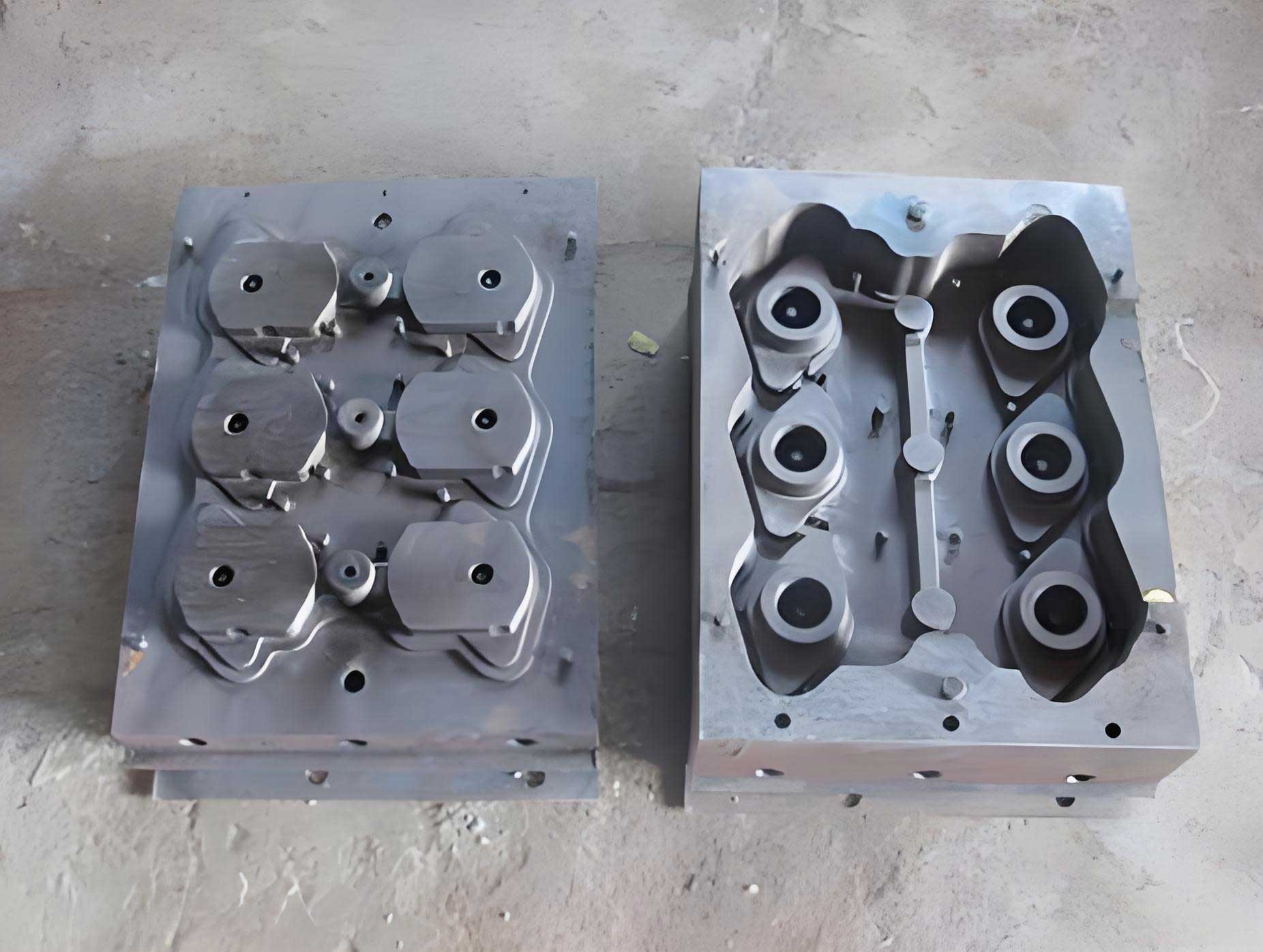
This image exemplifies the integrity of castings produced via sand coated iron mold casting, underscoring the importance of proper technique.
Despite its advantages, sand coated iron mold casting is prone to specific defects if not meticulously controlled. In my experience, the most common issues include shrinkage porosity, shrinkage cavities, sand inclusion, sand adhesion, gas pores, pinholes, and veining. Each defect stems from process variables unique to sand coated iron mold casting, and addressing them requires a deep understanding of the underlying mechanisms.
Shrinkage porosity and cavities are prevalent in sand coated iron mold casting due to the insulating effect of the sand layer, which reduces the chilling action of the iron mold and prolongs solidification. As the coating thickness increases, the risk of shrinkage defects rises, especially in thick-walled castings or those with prolonged pouring times. For example, in alloys with narrow freezing ranges—such as aluminum bronze, brass, high-grade cast iron, or alloyed cast iron—the solidification dynamics are critical. The solidification time \( t \) can be estimated using Chvorinov’s rule:
$$ t = k \left( \frac{V}{A} \right)^n $$
where \( V \) is the casting volume, \( A \) is the surface area, \( k \) is a constant dependent on mold material and casting conditions, and \( n \) is an exponent typically around 2. In sand coated iron mold casting, the sand layer alters the effective \( k \) value, increasing it compared to bare iron molds. To mitigate shrinkage, I recommend minimizing the sand coating thickness to the bare necessity for adhesion, slowing the pouring rate, dispersing gate positions, and lowering pouring temperatures to promote directional solidification. For instance, for a cylindrical casting, the modulus \( M = V/A \) can be calculated to design feeders; in sand coated iron mold casting, a reduced modulus may necessitate smaller feeders due to enhanced insulation.
Sand inclusion and adhesion defects in sand coated iron mold casting often arise from inadequate sand coating strength, leading to flaking or cracking, uneven or weak refractory coatings, high clay content in the sand lowering refractoriness, or improper baking. To combat this, I emphasize high compaction density during sand application, use of premium refractory coatings with good adhesion, thorough cleaning of the mold before pouring, and repair of any sand layer damage. The thermal stress during heating can be modeled using the heat conduction equation:
$$ \frac{\partial T}{\partial t} = \alpha \nabla^2 T $$
where \( T \) is temperature, \( t \) is time, and \( \alpha \) is thermal diffusivity. In sand coated iron mold casting, the sand layer’s lower \( \alpha \) compared to iron causes temperature gradients that may induce cracking if not controlled. Baking at controlled, low temperatures helps alleviate this.
Gas pores and pinholes in sand coated iron mold casting are typically caused by incomplete drying of the sand coating, moisture absorption during storage, or gas evolution from the mold itself. To prevent these, I ensure thorough baking of the sand coating or sleeves, preheating of iron molds, and incorporation of vent holes in the mold body. The gas pressure \( P \) in a pore can be related to the temperature \( T \) via the ideal gas law \( PV = nRT \), but in practice, maintaining dry conditions is key. For resin-bonded sands in sand coated iron mold casting, nitrogen or other gas generation must be managed through proper catalyst ratios and baking cycles.
Veining, or the formation of fine fins on castings, is another defect in sand coated iron mold casting, especially with resin sand coatings. It occurs when molten metal penetrates into the sand layer due to low coating compactness, poor sand refractoriness, or inadequate coating properties. To avoid veining, I strictly control the sand’s mechanical and thermal properties, ensuring uniform coating application and using high-toughness coatings. The penetration depth \( d \) can be approximated by Darcy’s law for flow in porous media:
$$ d = \sqrt{\frac{K \Delta P t}{\mu \phi}} $$
where \( K \) is permeability, \( \Delta P \) is pressure difference, \( t \) is time, \( \mu \) is viscosity, and \( \phi \) is porosity. In sand coated iron mold casting, reducing \( K \) through high compaction and using fine sands minimizes veining.
In summary, sand coated iron mold casting offers significant benefits: enhanced mold rigidity reduces casting distortion, allowing for riser-less or small-riser designs that boost yield; production efficiency improves with shorter cycles and lower costs; the process is relatively simple and operator-friendly, facilitating quality consistency; and it is exceptionally suited for cylindrical, sleeve, and ring-shaped castings. From my implementation of sand coated iron mold casting in industrial settings, I have seen firsthand how these advantages translate into reliable, high-performance components. The key lies in meticulous process control—from sand coating application to defect prevention—making sand coated iron mold casting a versatile and economical choice for modern foundries. By integrating theoretical models with practical adjustments, such as optimizing coating thicknesses and baking protocols, sand coated iron mold casting can achieve superior results across diverse applications, solidifying its role as a cornerstone of advanced casting technology.