
In my years of specialized foundry practice, the evolution and application of sand coated iron mold casting has been a focal point. This process, distinct from conventional green sand or resin sand casting, involves creating a thin, thermally conductive resin-bonded sand mold (the “coating”) adhered to the interior surfaces of a reusable iron mold. This hybrid method leverages the high chilling power and dimensional stability of the metal mold with the flexibility and surface finish afforded by the precision sand shell. Over the past decade and a half, its adoption has accelerated, particularly for thick-section castings requiring rapid solidification, establishing it as a vital component of modern foundry operations.
The comparative advantages are significant when juxtaposed with traditional methods. The process eliminates bulky sand boxes, utilizing a rigid iron mold that provides exceptional mold stiffness. This results in markedly reduced sand consumption, higher yield, and castings with superior dimensional accuracy, excellent surface finish, and reduced weight. However, sand coated iron mold casting is not a universal solution. Its limitations and specific challenges necessitate careful analysis for each component. The successful production of complex, thin-walled, or lengthy castings often requires tailored strategies to overcome inherent process constraints. This narrative details my firsthand experience in developing the process for a large box-type enclosure, focusing on the systematic resolution of defects such as surface blowholes, slag inclusions, and hot tears.
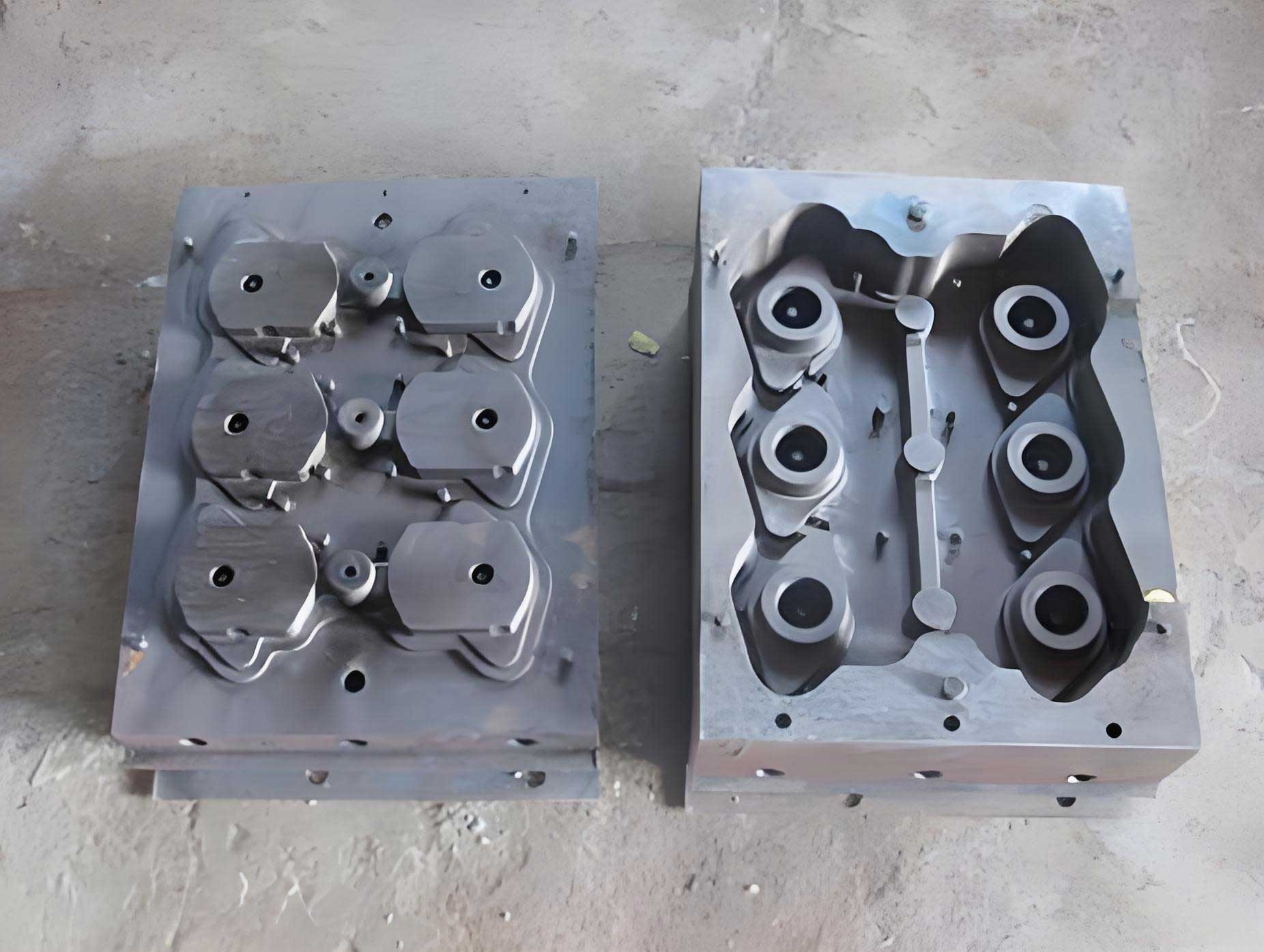
The subject casting, a gearbox housing, presented a notable challenge. Its material specification was GG25 (a German standard grey cast iron, analogous to Class 25). Geometrically, it was characterized by a nominal wall thickness of 8 mm, with localized sections swelling to 49 mm, creating a significant variation in thermal mass. The overall envelope dimensions were 970 mm in length, 520 mm in width, and 235 mm in height. The primary objective was to establish a robust sand coated iron mold casting process that could reliably produce this part meeting all dimensional, mechanical, and cosmetic requirements.
Process Design and Analysis
The foundational step involved designing the mold and gating system around the part geometry. We employed a standard mold frame of 1100 mm × 780 mm × 275 mm for the shooting and curing of the sand coating. The parting line was strategically placed on the primary flange face. The gating system was designed to feed from this flange plane, with the ingates also serving as feeders to compensate for shrinkage in the adjacent thick sections. Metallurgical control aimed at achieving the required tensile strength involved precise regulation of carbon and silicon equivalents and the addition of copper for alloy strengthening.
Two primary process schemes were conceived and critically analyzed:
| Scheme | Orientation | Advantages | Disadvantages & Risks |
|---|---|---|---|
| Scheme 1 | Casting in the lower mold half (drag). Gating on the flange face. | Simpler mold design. Natural feeding from the bottom via the flange. | High drop height (235 mm) for metal entering the cavity. High risk of mold erosion, turbulence, slag entrainment, and gas aspiration leading to defects on upper surfaces. |
| Scheme 2 | Casting in the upper mold half (cope). Gating on the flange face. | Potentially more quiescent fill as metal rises into the cavity. | High risk of mist runs, cold shuts, and gas porosity trapped on the extensive upper (now downward-facing) thin walls due to poor venting and premature freezing. |
The simulation of mold filling was instrumental in this decision. For sand coated iron mold casting, the high thermal conductivity of the iron mold accelerates solidification, making a turbulent fill particularly detrimental. While Scheme 2 offered a seemingly calmer fill, the inherent difficulty of venting gas from large, downward-facing areas in a process with a thin, impermeable sand coating posed a severe and potentially insurmountable challenge. The superior hot strength and lower gas generation of the coated shell compared to traditional green sand somewhat mitigated the risks of erosion in Scheme 1. Therefore, after weighing the evidence, Scheme 1 was selected for prototyping.
Key process parameters were established:
- Coating Thickness: A uniform 8 mm layer of resin-coated sand.
- Gating Ratio: The cross-sectional areas were balanced as Sprue : Runner : Ingate = 1 : 1.5 : 1.2, promoting a non-pressurized system to reduce velocity.
- Filtration: A 100 mm × 100 mm × 20 mm ceramic foam filter was placed at the sprue base to intercept slag and calm the metal stream.
- Core Process: Internal oil gallery cores, located deep within the drag, were made from a high-refractoriness, low-thermal-expansion coated sand and dipped in an alcohol-based zirconia paint to prevent burn-on and veining.
The metallurgical target for the iron was set with the following composition ranges (mass %):
$$C: 3.05\% – 3.25\%, \quad Si: 1.7\% – 1.9\%, \quad Cu: 0.6\% – 0.8\%$$
The final silicon, accounting for inoculation, was calculated to be approximately 2.0% to ensure the required pearlitic matrix and strength.
Initial Trial and Defect Manifestation
The trial procedure followed the standard sand coated iron mold casting sequence: mold heating to 200°C ± 50°C, sand shooting for 27 seconds, curing for 90-120 seconds, core setting, mold closing, and pouring. The pouring temperature was tightly controlled between 1420-1430°C, with a pouring time of 27-30 seconds. Shakeout was initially performed at 20-22 minutes after pouring.
Dimensional inspection via 3D scanning confirmed the process’s capability, with all critical dimensions within a ±1 mm tolerance band. An interesting observation was the differential shrinkage: the linear contraction in the width direction was 0.3% to 0.5% greater than in the length direction, a phenomenon attributable to the restraining effect of the iron mold and the part’s geometry.
However, the initial batch of seven castings revealed a pattern of quality issues that demanded immediate attention:
| Defect Type | Location | Frequency (7 castings) | Hypothesized Cause |
|---|---|---|---|
| Hot Tear / Crack | In side walls, near stress-concentrating features. | 3 | High mold restraint during the late stages of solidification/early cooling, combined with a long shakeout time. |
| Slag Inclusion | On vertical interior side walls. | 2 | Erosion of the sand coating during the high-drop fill, with eroded particles trapped before the filter. |
| Blowhole (Surface Porosity) | On the large upper flat surface. | 1 | Entrapped air or gas from the coating failing to vent through the parting line efficiently. |
Systematic Defect Analysis and Corrective Actions
The trial results, while showing some defects, provided a clear roadmap for process optimization. Each defect was addressed with a targeted countermeasure rooted in the physics of the sand coated iron mold casting process.
1. Mitigating Slag Inclusions on Side Walls
The slag inclusions were indicative of mold wall erosion. Despite the strength of the cured coating, the high kinetic energy of the initial metal stream falling 235 mm was sufficient to cause local scouring. The solution was to enhance the local refractory and erosional resistance of the shell at these critical points.
Action: A high-alumina, water-based refractory coating was manually sprayed onto the corresponding areas of the sand coating in the iron mold drag prior to core setting and closing. This added a protective, highly refractory layer that shielded the base sand from direct metal impingement and heat, effectively eliminating this defect in subsequent casts. The coating thickness was controlled to avoid altering the final casting dimensions.
2. Eliminating Blowholes on the Upper Plane
The blowholes on the cope surface suggested inadequate venting. In sand coated iron mold casting, the only paths for gas escape are through the parting line gap and any intentionally placed vents. The thin, cured sand shell itself has very low permeability.
Actions (Two-pronged approach):
- Overflow/Vent Risers: Four cylindrical overflow risers (Ø60 mm × 70 mm) were added to the pattern on the upper surface, diagonally opposite the main ingates. These served a dual purpose: they acted as excellent vents for air displaced by the advancing metal front, and they also trapped the first, possibly cooler and dirtier, metal to enter the cavity. The relationship for effective venting capacity can be considered by ensuring the total vent area is sufficient for the volumetric fill rate. While simplified, a necessary condition is:
$$A_v \geq \frac{Q}{v_g}$$
Where \(A_v\) is the total vent area, \(Q\) is the volumetric flow rate of metal, and \(v_g\) is the permissible velocity of gas escape (a function of gas type and back-pressure). The risers provided ample \(A_v\). - Parting Line Vent Gap: The clearance at the parting line was intentionally increased from a “metal-tight” fit to a controlled gap of 0.3-0.4 mm along the perimeter. This provided a continuous channel for gases to escape from the entire cavity periphery without causing flash.
3. Preventing Hot Tears and Cracks
Hot tears occur when the solidifying casting is subjected to tensile stress from mold restraint at a temperature where its strength is low but a coherent solid skeleton exists. The high rigidity of the iron mold in sand coated iron mold casting makes this a prominent risk, especially for parts with varying section thicknesses and geometric stress raisers.
Analysis: The initial shakeout time of 20-22 minutes meant the casting was cooling almost entirely within the confines of the rigid iron mold. The differential cooling rates between thick hubs (49 mm) and thin walls (8 mm) created significant internal stresses. The casting needed to be freed from the mold’s constraint at a higher temperature, allowing it to contract more freely during the most critical phase.
Action: The shakeout time was drastically reduced to 13-15 minutes post-pouring. This required careful determination to ensure the casting was mechanically solid enough to handle without distortion but still hot enough to be plastic. The new time was based on empirical observation and a simplified estimate of solidification time for the thickest section using Chvorinov’s Rule:
$$ t_s = B \cdot \left( \frac{V}{A} \right)^n $$
Where \( t_s \) is solidification time, \( V \) is volume, \( A \) is surface area, \( B \) is a mold constant (very high for chilled iron molds), and \( n \) is an exponent (~2). For the 49-mm thick section, its modulus \( (V/A) \) is high, leading to a longer \( t_s \). Shakeout at 13-15 minutes occurred when the thinner walls were fully solid and strong, but the thermal center of the thick sections was still above the brittle temperature range, allowing stress relief through plastic deformation rather than cracking.
Results and Concluding Insights
Implementing this suite of corrective measures—local coating, overflow risers, increased venting, and early shakeout—resulted in a dramatic improvement. A follow-up production batch showed the virtual elimination of the targeted blowhole, slag inclusion, and hot tear defects. The castings met all specifications:
- Quality: Sound castings free from the major defects.
- Mechanical Properties: Hardness ranged from 192 to 200 HBW on the casting body.
- Microstructure: A fine, Type A graphite distribution (ASTM size 4) within a pearlitic matrix, confirming the effectiveness of the metallurgical control and the chilling effect of the sand coated iron mold casting process.
- Machinability: Excellent, with no hard spots or inclusions disrupting tool life.
| Aspect | Initial Parameter | Optimized Parameter | Rationale |
|---|---|---|---|
| Process Scheme | Scheme 1 (Casting in Drag) | Scheme 1 with modifications | Preferred over Scheme 2 due to better venting potential for large flat surfaces. |
| Local Mold Coating | None | Water-based refractory spray on critical drag areas | Prevents sand erosion and slag formation from high-drop filling. |
| Venting | Basic parting line | 4 Overflow risers + 0.3-0.4 mm parting line gap | Provides positive venting path for air and early-metal contaminants. |
| Shakeout Time | 20-22 minutes | 13-15 minutes | Reduces mold restraint during vulnerable cooling phase to prevent hot tears. |
| Pouring Temperature | 1420-1430°C | 1420-1430°C (maintained) | Ensures fluidity for thin walls while minimizing thermal shock to mold. |
This case study underscores that sand coated iron mold casting is a powerful but demanding technology. Its success hinges on a deep understanding of the interplay between thermal management (dictated by the iron mold), fluid flow dynamics (in a fast-solidifying environment), and stress evolution. For complex box-type castings with large planar areas and section variations, proactive measures are non-negotiable. The integration of simulation for filling analysis, strategic use of coatings and overflows, and precise control over the thermal cycle—particularly the shakeout timing—are proven effective strategies. This holistic approach transforms the inherent challenges of the process into reliable, high-quality production, fulfilling the promise of precision, efficiency, and performance that sand coated iron mold casting offers to the modern foundry industry.