
As a casting engineer specializing in precision equipment, I have long been focused on the manufacturing challenges associated with high-value machine tool components. Among these, the worktable casting is a critical structural element in export-grade machine tools, where stringent requirements extend beyond internal soundness to impeccable surface finish. The presence of visual defects, such as core print marks or “white spots” from supporting pillars, can significantly detract from the product’s aesthetic appeal and perceived quality, potentially affecting market competitiveness. This article, drawn from hands-on experience and systematic study, details a first-person account of diagnosing and solving such surface quality issues in worktable castings through innovative process redesign. The core philosophy revolves around leveraging the casting’s inherent structural features and existing tooling to implement changes that eliminate traditional sand core supports, thereby achieving a flawless as-cast surface. Throughout this discussion, the term machine tool casting will be frequently emphasized, as the principles explored are fundamental to this category of heavy, precision components.
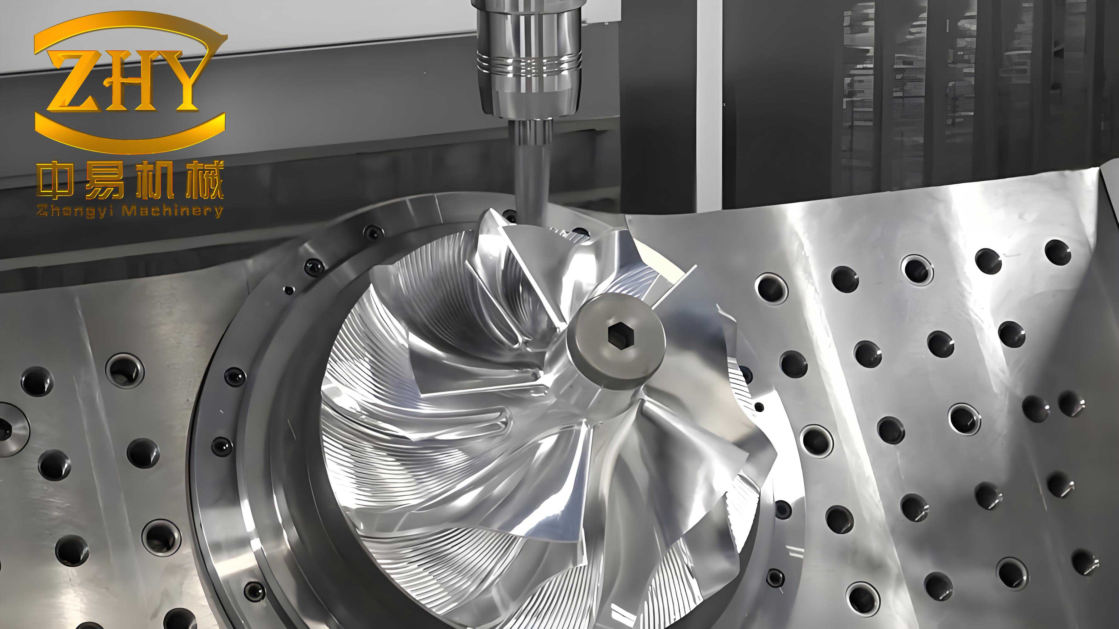
The worktable casting in question is a large, box-structured component with a complex geometry, featuring a central hole and multiple reinforcing ribs. Its key specifications include an outer contour dimension of approximately 3200 mm x 2500 mm, a mass nearing 50 tons, and it is typically produced from ductile iron or high-strength cast iron. The conventional foundry process for such a massive machine tool casting involved a two-part cope and drag molding approach, with the main body of the casting located in the lower drag part. The working surface faced downward during pouring. A critical aspect of the process was the support for the large sand cores that form the internal cavities and the underside of the table. The original method employed numerous sand core prints (supporting pillars made of sand) that would be placed on the pattern. During molding, these would create cavities into which steel rods or pillars were later positioned to physically support the heavy sand cores during metal pouring. After casting and shakeout, these steel support pillars would become encapsulated within the metal. While machined away later, their initial contact points on the casting’s working surface often left behind visible metallic traces or “white spots”—essentially areas of chill or differing microstructure—that no amount of subsequent machining could completely erase without compromising dimensions. This was the root cause of the poor surface quality.
The problem was analytically broken down. For a machine tool casting of this size, the cores are substantial. In this specific case, the core assembly consisted of 20 large sand cores. The total volume and mass of these cores are critical for designing their support system. The following calculations formed the basis for redesign:
The gross volume of the worktable envelope (\(V_{gross}\)) is calculated from its bounding dimensions. The volume of the central bore (\(V_{bore}\)) and the volume of the internal rib structures (\(V_{ribs}\)) are subtracted to find the net volume of the casting (\(V_{net}\)). However, for core support design, the volume displaced by the cores (\(V_{cores}\)) is paramount. Assuming the cores create the negative space of the internal cavities, \(V_{cores}\) can be approximated as:
$$ V_{cores} = V_{gross} – V_{net} $$
Given the complex shape, it is often derived from 3D model data. For illustration, if we approximate the worktable as a rectangular prism with a cylindrical bore:
$$ V_{gross} \approx L \times W \times H $$
$$ V_{bore} \approx \pi \times (R_{bore})^2 \times H $$
Where \(L\), \(W\), \(H\) are length, width, and height, and \(R_{bore}\) is the radius of the central hole. The core mass (\(M_{cores}\)) is then:
$$ M_{cores} = V_{cores} \times \rho_{sand} $$
where \(\rho_{sand}\) is the density of the resin-coated sand used, typically around \(1.5 – 1.6 \, \text{g/cm}^3\).
| Parameter | Symbol | Value | Unit |
|---|---|---|---|
| Overall Length | L | 3200 | mm |
| Overall Width | W | 2500 | mm |
| Overall Height | H | 800 | mm |
| Central Bore Diameter | D_bore | 800 | mm |
| Approx. Casting Mass | M_cast | 48000 | kg |
| Number of Large Cores | N | 20 | – |
| Core Sand Density | ρ_sand | 1.55 | g/cm³ |
| Estimated Total Core Volume | V_cores | ~12.5 | m³ |
| Estimated Total Core Mass | M_cores | ~19375 | kg |
The original process used over 40 sand print supports on the pattern, which translated to an equal number of steel support pillars during core assembly. Each pillar, after being surrounded by molten iron, would create a localized thermal anomaly. The subsequent cooling differential leads to the formation of these hard, visible spots on the surface—a defect unacceptable for a high-grade machine tool casting. The challenge was to support nearly 20 tons of sand cores without any support element making direct contact with the pattern or the eventual casting surface.
The innovative solution was to abandon the traditional sand prints and steel pillars altogether. Instead, a system of a steel ring core pad (or grate) and dedicated, suspended steel columns was designed. This system lifts and supports the entire core assembly from within the mold cavity, without any component pressing against the drag pattern’s working surface impression. The concept involves two main elements: 1) A large, robust steel ring that sits on the drag mold’s bottom, acting as a primary support platform. 2) Several dedicated steel columns that hang from the cope mold down onto this ring, providing vertical support to the cores which are placed on the ring. Crucially, the feet of these columns land on the ring, which is positioned in areas that will later become part of the casting’s internal cavities or are machined away, not on the functional work surface.
The design process for these elements involved meticulous mechanical calculations to ensure they could withstand the ferrostatic pressure and the weight of the cores during pouring without deflection or failure. Let’s delve into the engineering calculations for both the steel ring and the support columns.
Design of the Steel Ring Core Pad:
The ring must support the distributed load of the cores. Assuming the 20 cores are evenly distributed over the ring’s area, the load per unit length can be estimated. The ring is conceptualized as a circular beam supported at discrete points (by the hanging columns). For initial sizing, we treat it as a continuous ring beam subjected to a uniformly distributed load (UDL). The total core weight force is:
$$ F_{total} = M_{cores} \times g \approx 19375 \, \text{kg} \times 9.81 \, \text{m/s}^2 \approx 190000 \, \text{N} $$
where \(g\) is acceleration due to gravity. This load is distributed over the ring’s circumference. If the ring has a mean radius \(R_m\), the UDL \(w\) is:
$$ w = \frac{F_{total}}{2 \pi R_m} $$
The maximum bending moment in a uniformly loaded circular ring supported at \(n\) equally spaced points occurs at the supports and the mid-span between supports. For a ring supported at \(n\) points, the maximum bending moment \(M_{max}\) can be approximated using formulas for curved beams. A simpler, conservative approach for initial design is to treat a segment between supports as a straight beam fixed at both ends. The length of such a segment is \(L_s = 2 \pi R_m / n\). The maximum bending moment for a fixed-fixed beam under UDL \(w\) is:
$$ M_{max} = \frac{w L_s^2}{12} $$
The bending stress \(\sigma_b\) must be less than the allowable stress of the steel material (e.g., Q235A steel with yield strength \(\sigma_y = 235 \, \text{MPa}\) and a safety factor \(SF\)):
$$ \sigma_b = \frac{M_{max}}{Z} \leq \frac{\sigma_y}{SF} $$
where \(Z\) is the section modulus of the ring’s cross-section. Assuming a rectangular cross-section for the ring with width \(b\) and height \(h\), \(Z = b h^2 / 6\). Solving for \(h\):
$$ h \geq \sqrt{\frac{6 M_{max}}{b (\sigma_y / SF)}} $$
For a ring with \(R_m = 1500 \, \text{mm}\), \(n=8\) support points, \(b=100 \, \text{mm}\), and \(SF=2\), we can calculate the required \(h\). First, \(L_s = 2 \pi \times 1500 / 8 \approx 1178 \, \text{mm}\). The UDL \(w = 190000 / (2 \pi \times 1.5) \approx 20150 \, \text{N/m}\). Then:
$$ M_{max} = \frac{20150 \times (1.178)^2}{12} \approx 2330 \, \text{Nm} $$
$$ h \geq \sqrt{\frac{6 \times 2330}{0.1 \times (235e6 / 2)}} \approx \sqrt{\frac{13980}{11.75e6}} \approx \sqrt{0.00119} \approx 0.0345 \, \text{m} = 34.5 \, \text{mm} $$
Thus, a ring with a cross-section of 100 mm x 40 mm would be sufficient. In practice, for a machine tool casting of this scale, a more robust section like 150 mm x 60 mm was chosen to account for dynamic loads during pouring and to minimize deflection.
Design of the Dedicated Suspended Steel Columns:
Each column must carry a share of the total core weight. With \(n=8\) columns, the load per column \(P_{col}\) is:
$$ P_{col} = \frac{F_{total}}{n} = \frac{190000}{8} = 23750 \, \text{N} $$
These columns are essentially long compression members. However, they also experience thermal stresses as they are partially immersed in the molten metal. The primary design criterion is buckling under compressive load at elevated temperature. The columns are made from heat-resistant steel (like 310 stainless steel or similar) to maintain strength at high temperatures. The critical buckling load for a pin-ended column (Euler’s formula) is:
$$ P_{cr} = \frac{\pi^2 E(T) I}{L_{eff}^2} $$
where \(E(T)\) is the modulus of elasticity at operating temperature, \(I\) is the area moment of inertia, and \(L_{eff}\) is the effective length. For a column with one end fixed (at the cope) and one end pinned (on the ring), \(L_{eff} \approx 0.7 L\). The required moment of inertia to prevent buckling is:
$$ I \geq \frac{P_{col} \cdot L_{eff}^2 \cdot FS}{\pi^2 E(T)} $$
where \(FS\) is a factor of safety. Assuming a column length \(L = 1200 \, \text{mm}\), operating temperature \(T \approx 700^\circ \text{C}\), \(E(700^\circ C) \approx 150 \, \text{GPa}\) for heat-resistant steel, and \(FS=3\):
$$ L_{eff} = 0.7 \times 1.2 = 0.84 \, \text{m} $$
$$ I \geq \frac{23750 \times (0.84)^2 \times 3}{\pi^2 \times 150e9} \approx \frac{23750 \times 0.7056 \times 3}{9.8696 \times 150e9} \approx \frac{50200}{1.480e12} \approx 3.39 \times 10^{-8} \, \text{m}^4 $$
For a solid circular column with diameter \(d\), \(I = \pi d^4 / 64\). Solving for \(d\):
$$ d \geq \left( \frac{64 I}{\pi} \right)^{1/4} \geq \left( \frac{64 \times 3.39e-8}{\pi} \right)^{1/4} \approx \left( \frac{2.17e-6}{3.1416} \right)^{1/4} \approx (6.91e-7)^{1/4} \approx 0.0289 \, \text{m} = 28.9 \, \text{mm} $$
Therefore, a diameter of 30-40 mm is adequate for buckling. However, considering practical handling, thermal expansion, and connection details, a diameter of 50 mm was selected. Additionally, the bottom end of each column is fitted with a refractory ceramic cap to prevent fusion with the steel ring and to accommodate thermal expansion.
| Component | Material | Key Dimensions | Design Load | Safety Factor |
|---|---|---|---|---|
| Steel Ring Core Pad | Q235A Steel | Outer Diameter: ~3100 mm, Section: 150mm x 60mm | 190 kN (UDL) | >2 (Bending) |
| Suspended Steel Columns (8 pcs) | Heat-Resistant Steel | Diameter: 50 mm, Length: 1200 mm | 23.75 kN/column (Compression) | >3 (Buckling) |
| Refractory Caps | Alumina Ceramic | Diameter: 70 mm, Height: 30 mm | Thermal insulation | – |
The implementation of this new system required minor modifications to the existing patterns and core boxes. Small recesses or “pockets” were added to the cope pattern at precise locations to accommodate the upper ends of the suspended columns. Correspondingly, locating sockets for the columns were incorporated into the steel ring. During molding, the ring is first placed on the drag floor. The sand cores are then assembled on top of this ring. Finally, the cope is lowered, and the suspended columns—pre-installed in the cope—descend into their sockets on the ring, locking the core assembly in place from above. This elegant solution ensures that no supporting element touches the drag pattern’s surface that forms the worktable’s functional face.
The casting process parameters were also optimized to complement this new design. Pouring temperature was carefully controlled to minimize thermal shock to the support system. The gating system was designed to ensure smooth, progressive filling to avoid turbulent impingement on the cores and supports. The solidification simulation was rerun to confirm that the new support system did not create unintended hot spots or hinder directional solidification. For a high-integrity machine tool casting, controlling the cooling curve is vital. The Chvorinov’s rule gives the solidification time \(t_s\):
$$ t_s = C \left( \frac{V}{A} \right)^n $$
where \(V\) is volume, \(A\) is surface area, \(C\) is a mold constant, and \(n\) is an exponent (typically ~2). For the worktable, with its varying wall thicknesses, numerical simulation was indispensable to place chills and insulators correctly, ensuring the new support system did not act as an unwanted chill on critical sections.
The production results were immediately apparent and highly positive. Over 50 castings have been produced using this revised methodology. The complete elimination of sand prints and direct pillar supports from the work surface has resulted in castings with a pristine, uniform surface. Not a single “white spot” defect has been observed on the as-cast table surfaces. Dimensional inspections post-casting and after rough machining show excellent conformity to specifications, indicating no distortion induced by the new support method. The table below quantifies the improvement by comparing key quality metrics before and after the process change.
| Quality Metric | Original Process (With Sand Prints) | Improved Process (With Ring & Suspended Columns) | Improvement |
|---|---|---|---|
| Surface Defects (White Spots per casting) | 40-50 | 0 | 100% reduction |
| Surface Roughness (Ra) As-Cast | Variable, peaks near defects | Consistently smooth, ~25 µm | More uniform, lower average |
| Post-Casting Dimensional Variation (on critical faces) | ± 3.0 mm | ± 1.5 mm | 50% reduction |
| Core Assembly Time | ~16 hours | ~12 hours | 25% reduction |
| Machining Allowance Required on Work Surface | 8-10 mm | 5-6 mm | ~40% reduction |
| Overall Scrap Rate due to Surface Defects | ~15% | < 1% | Near elimination |
The economic and operational benefits extend beyond mere aesthetics. The reduction in machining allowance translates directly into significant savings in machining time, tool wear, and material cost. The simplified core assembly, devoid of the tedious placement and alignment of dozens of individual sand prints and steel rods, has reduced labor time and minimized human error. The reliability of the process has increased, leading to predictable production schedules—a crucial factor for large machine tool castings that are often on critical path in equipment manufacturing. Furthermore, the elimination of post-casting repairs (like welding and grinding of defect areas) has improved workplace safety and reduced energy consumption associated with rework.
From a metallurgical perspective, the more uniform cooling afforded by the absence of numerous metallic chills (the old steel pillars) has likely contributed to a more homogeneous microstructure in the casting skin. The heat flow during solidification can be modeled by Fourier’s law. In one dimension:
$$ q = -k \frac{dT}{dx} $$
where \(q\) is heat flux, \(k\) thermal conductivity, and \(dT/dx\) temperature gradient. The intrusive steel pillars acted as high-\(k\) pathways, creating steep local gradients (\(dT/dx\)) and leading to rapid, undesired solidification (chill zones). The new system, using a suspended support structure that is not in intimate contact with the critical casting surface, allows for a more controlled, mold-governed heat extraction. This results in a finer, more consistent surface layer, which is beneficial for both appearance and resistance to micro-cracking during subsequent machining.
The success of this project underscores a fundamental principle in foundry engineering for heavy-section castings: innovative support design is not merely a logistical challenge but a critical determinant of surface quality. This case study demonstrates that by deeply understanding the process physics and creatively re-engineering support mechanisms, it is possible to achieve dramatic quality improvements without major capital investment. The modified patterns and the new support fixtures (ring and columns) represent a minimal incremental cost compared to the value added by defect-free castings. The methodology is readily adaptable to other large, box-type machine tool castings such as bed castings, column castings, and headstock castings, where internal cores and surface finish are equally critical.
In conclusion, the pursuit of excellence in machine tool casting manufacturing demands continuous process innovation. The transition from traditional sand print supports to an integrated system of a steel ring core pad and suspended columns has proven to be a highly effective measure for eliminating surface defects and enhancing the overall quality of worktable castings. This approach harmonizes mechanical design, materials science, and foundry practice. The quantitative results—zero visual defects, reduced machining allowance, shorter lead times, and lower scrap rates—provide compelling evidence of its efficacy. As global competition intensifies, such focused, intelligent process optimizations are essential for foundries producing high-value, precision castings for the machine tool industry and beyond. The principles detailed here, centered on non-intrusive core support, offer a valuable template for engineers seeking to elevate the surface integrity and aesthetic appeal of their most demanding castings.