
The production of high-quality machine tool castings, which form the structural backbone of lathes, milling machines, grinders, and other precision equipment, presents a unique set of challenges. These castings are typically characterized by large dimensions, intricate geometries, significant variations in wall thickness, and complex internal ribbing. The modern manufacturing landscape demands rapid prototyping, frequent design updates, and the ability to produce small batches with consistently high quality. These requirements often render traditional green sand molding with intricate core assemblies economically and technically unviable due to high tooling costs, dimensional inaccuracies, and complex processes. Consequently, the Full Mold Casting (FMC) process, utilizing Expanded Polystyrene (EPS) patterns, has become a cornerstone in the foundry industry for producing these complex machine tool castings.
Full Mold Casting offers distinct advantages for machine tool castings, including excellent dimensional accuracy, superior surface finish, design flexibility, and a significantly shortened lead time from design to finished casting. However, the success of this process hinges critically on the design of the gating system, particularly the configuration of the in-gates or runners that deliver molten metal into the mold cavity. The shape and dimensions of these runners directly influence flow characteristics, solidification patterns, and ultimately, the integrity of the final casting.
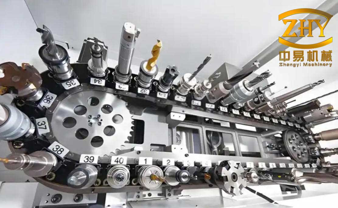
While circular cross-sections are often preferred in fluid dynamics for minimizing frictional losses and promoting laminar flow, the complex and confined geometries inherent in many machine tool castings frequently preclude their use. It is within this constraint that the “duckbill” style runner, featuring a transition from a circular inlet to a rectangular (flat) outlet, has found practical application. This article explores the implementation, fluid-dynamic analysis, advantages, and limitations of this specialized gating component in the context of Full Mold Casting for machine tool castings.
Fluid Dynamics of Gating: The Ideal vs. The Practical
From a purely hydrodynamic perspective, a circular cross-section is optimal for conduit flow. The Navier-Stokes equations describe this behavior, indicating that a circular pipe minimizes the perimeter for a given cross-sectional area, thereby reducing wall friction and promoting stable flow. For an incompressible fluid in steady flow, the continuity equation governs the relationship between cross-sectional area and velocity:
$$Q = v_1 A_1 = v_2 A_2 = \text{constant}$$
where \(Q\) is the volumetric flow rate, \(v\) is the flow velocity, and \(A\) is the cross-sectional area. This principle implies that for a constant flow rate, the velocity is inversely proportional to the area. In an ideal, straight circular runner, this leads to predictable and relatively smooth flow.
However, the design of machine tool castings often includes narrow sections, ribs, or walls with thicknesses in the range of 15-20 mm. Installing a standard circular ceramic runner with a diameter sufficient for adequate feed (e.g., 40-50 mm) in such locations is physically impossible without causing significant mold wall weakness or “sink” defects at the connection point. The traditional workaround involves adding an EPS foam pad or “padding” at the runner attachment site to increase local wall thickness. This method, however, introduces a new thermal mass, creating a hotspot that can lead to shrinkage porosity as the casting solidifies, negating the purpose of effective feeding. It also complicates pattern assembly and finishing operations.
The “Duckbill” Runner: Design and Implementation
The “duckbill” runner is engineered as a solution to this spatial conflict. It is a prefabricated tube, typically made from ceramic or fiber-reinforced paper, that features a circular inlet at one end (for connection to the downsprue or horizontal runners) and a flattened, rectangular outlet at the other. This shape allows the exit to be placed against a thin wall of the machine tool casting pattern, minimizing the required contact area and eliminating the need for large foam pads.
The design parameters of a “duckbill” runner can be summarized by its key dimensions, which influence its performance:
| Parameter | Description | Typical Range / Consideration |
|---|---|---|
| Inlet Diameter (Din) | Circular opening connecting to main gating. | 30 mm – 50 mm (matches main runner size). |
| Outlet Width (Wout) | Width of the rectangular exit section. | Adapts to casting wall thickness (e.g., 20-30 mm). |
| Outlet Height (Hout) | Height (or gap) of the rectangular exit. | Designed for target cross-sectional area; often 5-10 mm for a thin, wide gate. |
| Transition Length (Lt) | Length over which the cross-section transforms. | Critical for flow stability; longer transitions reduce turbulence. |
| Aspect Ratio (Wout/Hout) | Ratio of outlet width to height. | High aspect ratio creates a “choke” effect, promoting rapid freezing. |
The cross-sectional area at the inlet (Ain) and the outlet (Aout) is ideally kept equal or with a slight taper to maintain pressure according to Bernoulli’s principle, simplified for horizontal flow without major height changes:
$$P_1 + \frac{1}{2} \rho v_1^2 = P_2 + \frac{1}{2} \rho v_2^2$$
where \(P\) is pressure and \(\rho\) is fluid density. If \(A_{in} = A_{out}\), then theoretically \(v_1 = v_2\). However, the abrupt or constrained change in geometry disrupts this ideal condition.
Hydrodynamic Analysis and Flow Behavior
The fundamental challenge with the “duckbill” runner lies in its violation of the streamlined flow path ideal. As the molten metal (primarily iron for machine tool castings) flows from the circular section into the transitional zone, the fluid streamlines are compressed and redirected. This geometric constriction, even if the nominal area is maintained, causes a phenomenon known as vena contracta, where the effective flow area is temporarily reduced below the physical area of the opening.
The coefficient of contraction (\(C_c\)) defines this relationship:
$$A_{effective} = C_c \cdot A_{physical}$$
For a sharp-edged orifice or a sudden contraction, \(C_c\) can be as low as 0.65. In the transitional section of the duckbill, a similar effect occurs, leading to a localized increase in velocity (\(v_{local}\)):
$$v_{local} = \frac{Q}{A_{effective}} = \frac{Q}{C_c \cdot A_{physical}} > \frac{Q}{A_{physical}}$$
This accelerated, squeezed flow becomes inherently unstable. The velocity profile, which is nearly parabolic in a long, straight circular pipe, becomes distorted. High-velocity jets form in the center, while slower-moving fluid interacts strongly with the walls of the transitioning geometry. This creates significant shear forces and velocity gradients, which are the primary sources of turbulence. The Reynolds number (\(Re\)), which predicts the transition from laminar to turbulent flow, is exceeded:
$$Re = \frac{\rho v D_h}{\mu}$$
where \(D_h\) is the hydraulic diameter and \(\mu\) is the dynamic viscosity. The irregular geometry and high local velocities ensure \(Re\) is well into the turbulent regime. This turbulence manifests as chaotic eddies and vortices within the runner and at the point of entry into the mold cavity.
In conventional sand casting, such turbulence is highly undesirable as it promotes:
- Air Entrainment: Vortices can draw air from the mold cavity or the runner itself into the molten metal stream.
- Slag/Dross Entrapment: Turbulent flow prevents buoyant oxides and impurities from floating to the top of the sprue/runner; instead, they are churned back into the metal.
- Mold Erosion: High-velocity, chaotic flow can scour the sand mold, leading to sand inclusions.
However, the context of Full Mold Casting for machine tool castings alters this perspective. In FMC, the EPS pattern vaporizes upon contact with the molten metal, producing gaseous and liquid pyrolysis products. A certain degree of controlled turbulence at the metal front can be beneficial in helping to break up and evacuate these decomposition products from the mold cavity, potentially reducing defects like carbonaceous folds (lustrous carbon) or slag patches related to foam residue.
Advantages in the Production of Machine Tool Castings
Despite its turbulent flow characteristics, the “duckbill” runner offers several compelling advantages specifically for the production of complex machine tool castings via the FMC process:
1. Spatial Adaptability and Design Freedom: This is the primary advantage. It enables the placement of an effective ingate in locations where a circular runner of equivalent feed capacity simply cannot fit, allowing foundry engineers greater flexibility in designing gating systems for intricate machine tool castings.
2. Controlled Freezing and Feeding for Gray Iron: Machine tool castings are predominantly made from gray iron, which undergoes significant graphite expansion during the latter stages of solidification. The flat, rectangular outlet of the “duckbill” runner has a high surface-area-to-volume ratio and a smaller modulus (volume/area) compared to a circular runner of the same cross-sectional area.
The solidification time can be approximated by Chvorinov’s Rule:
$$t_s = B \left( \frac{V}{A} \right)^n$$
where \(t_s\) is solidification time, \(V\) is volume, \(A\) is surface area, \(B\) is a mold constant, and \(n\) is an exponent (~2). The lower modulus \((V/A)\) of the flat section causes it to solidify and “seal off” more quickly than the adjacent casting section or a thicker, circular ingate. In gray iron, this early closure of the ingate traps the internal pressure generated by graphite expansion within the casting, effectively using this expansion to compensate for the liquid and solidification shrinkage of the iron itself. This mechanism significantly reduces the risk of shrinkage porosity in the critical areas fed by these runners, which is paramount for the structural integrity of machine tool castings.
3. Ease of Removal and Finishing: The thin, flat section of the runner attached to the casting is mechanically weaker than a circular lug. This allows for easier and cleaner removal during the knockout and finishing stages, reducing grinding time and consumable costs—a significant factor in the high-volume finishing typical of large machine tool castings.
4. Elimination of Foam Pads: By integrating the necessary geometry into the runner itself, it removes the need for separate, error-prone foam padding, simplifying pattern assembly, improving dimensional consistency at the gating point, and eliminating the associated thermal hot spot.
Limitations and Practical Considerations
The application of “duckbill” runners requires careful consideration of their inherent drawbacks:
1. Induced Turbulence and Defect Risk: As analyzed, the flow is inherently turbulent. While some turbulence may be tolerated in FMC, excessive agitation increases the risk of re-oxidation dross formation and gas entrapment within the metal stream before it even enters the mold cavity. This can lead to subsurface pinholes or dross inclusions in the final machine tool castings.
2. Sensitivity to Design Parameters: The performance is highly sensitive to the transition length (\(L_t\)) and the aspect ratio of the outlet. A too-short transition or an overly severe contraction will exacerbate turbulence and vena contracta effects. Empirical testing and computational fluid dynamics (CFD) simulation are recommended to optimize these parameters for specific machine tool casting applications.
3. Not a Universal Solution: It is a compromise for constrained spaces. For open areas on a casting where a circular, tapered runner can be used without causing defects, the circular runner remains the superior hydrodynamic choice for promoting cleaner, quieter metal entry.
4. Potential for Premature Freezing: If the outlet section is too thin (excessively high aspect ratio), it may freeze shut before the mold cavity is completely filled, especially in slower-pouring sections or with lower-temperature metal, leading to mistruns.
| Feature | Circular Runner | “Duckbill” Runner |
|---|---|---|
| Flow Character | More laminar, stable. | Turbulent, disturbed. |
| Spatial Requirement | High (requires radial clearance). | Low (fits against flat walls). |
| Solidification Rate | Slower (higher modulus). | Faster (lower modulus). |
| Feeding Mechanism (Gray Iron) | May stay open too long, risking “reverse shrinkage”. | Closes early, utilizes graphite expansion effectively. |
| Defect Tendency | Lower gas/dross entrainment. | Higher potential for turbulence-related defects. |
| Finishing Ease | More difficult to remove. | Easier to knock off and clean. |
| Primary Application | Open areas, preferred for clean metal delivery. | Confined areas, complex junctions in machine tool castings. |
Case Study and Defect Correlation in Machine Tool Castings
In a production setting for a large CNC machining center bed casting, “duckbill” runners were employed at several locations where internal ribbing converged. The casting material was Class 35 gray iron. Gating design aimed to balance flow with the early freezing benefit.
Process Parameters:
- Metal Pouring Temperature: 1380°C
- Pattern Material: Density 24 kg/m³ EPS
- Mold Sand: Self-setting silicate sand
- Runner Outlet Dimensions: 60mm (W) x 8mm (H)
Post-casting analysis over a batch of 30 pieces revealed a specific defect profile. The defect occurrence, mapped against runner type, is summarized below:
| Defect Type | Near Circular Runners (%) | Near “Duckbill” Runners (%) | Root Cause Correlation |
|---|---|---|---|
| Shrinkage Porosity/Cavities | 8% | 2% | Effective use of graphite expansion due to early gate freeze. |
| Subsurface Pinholes (Gas) | 3% | 7% | |
| Slag/Dross Inclusions | 4% | 9% | |
| Sand Inclusions (Erosion) | 5% | 6% | Similar rate; attributed more to overall mold strength than runner type. |
| Incomplete Filling (Mistrun) | 1% | 4% |
The data clearly supports the theoretical analysis: “duckbill” runners were highly effective in suppressing shrinkage defects in these gray iron machine tool castings, showcasing their primary benefit. However, this came at the cost of a statistically higher incidence of gas-related pinholes and dross inclusions, directly linked to the turbulent metal entry and air entrainment. The occurrence of mistruns near some “duckbill” gates pointed to instances where the outlet area or design might have been too restrictive, causing premature freezing during filling. This highlights the critical need for precise design and area calculation.
Conclusion and Future Directions
The “duckbill” runner is a pragmatic and valuable tool in the foundry engineer’s arsenal for producing complex machine tool castings via the Full Mold process. Its design is a direct response to the geometric conflicts posed by intricate casting designs. Its foremost strength lies in its ability to be placed in confined spaces and, crucially, to solidify rapidly in gray iron applications, thereby harnessing the metallurgical expansion of graphite to achieve sound, dense castings with minimal shrinkage.
However, its adoption is not without compromise. The inherent turbulent flow it generates increases the susceptibility to gas and dross defects. Therefore, its use must be strategic. It is not a wholesale replacement for well-designed circular gating but rather a specialized solution for specific problem areas on a machine tool casting. The decision to use it should follow a careful assessment: when the risk of shrinkage in a hard-to-feed section outweighs the increased risk of turbulence-related defects.
Future work should focus on optimizing the “duckbill” design to mitigate its weaknesses. This includes:
- Parametric CFD Studies: Systematically simulating the effects of transition length (Lt), outlet aspect ratio, and inlet-to-outlet area ratio on flow stability, vena contracta, and shear stress to establish optimal design guidelines.
- Material Development: Exploring runner materials with improved thermal properties or internal coatings that can help stabilize flow or reduce heat loss at the thin section to prevent mistruns.
- Integrated Design Rules: Developing empirical formulas or charts that link machine tool casting wall thickness, required feed volume, and iron grade to recommended “duckbill” outlet dimensions and transition geometry.
In summary, for the production of high-integrity machine tool castings, the “duckbill” runner serves as a critical enabling technology for the Full Mold process. Its intelligent application, grounded in an understanding of both its solidification advantages and its fluid dynamic drawbacks, allows foundries to navigate the complex trade-offs involved in casting these large, intricate components, ultimately contributing to the manufacture of more reliable and precise machine tools.