
In my years of experience as a foundry engineer specializing in heavy machinery, I have consistently encountered the formidable challenges associated with producing large, intricate machine tool castings. These castings, such as beds, frames, and columns, form the structural backbone of precision machine tools. Their geometry is inherently complex, often featuring deep sections, thin walls, internal ribs, and critical guideway surfaces that demand exceptional dimensional stability, hardness, and freedom from defects like porosity, shrinkage, and slag inclusions. The quality and performance of the final machine tool are directly and profoundly influenced by the casting process. Among all process variables, the design of the gating and feeding system stands out as the most critical determinant of quality stability. A poorly designed system can lead to catastrophic failures, while a well-engineered one ensures reproducibility and high yield. This article, drawn from hands-on practice, delves into the detailed analysis and iterative refinement of process designs for two representative large machine tool castings. I will share insights, supported by technical data, formulas, and comparative tables, to illustrate the nuanced decision-making required in this field.
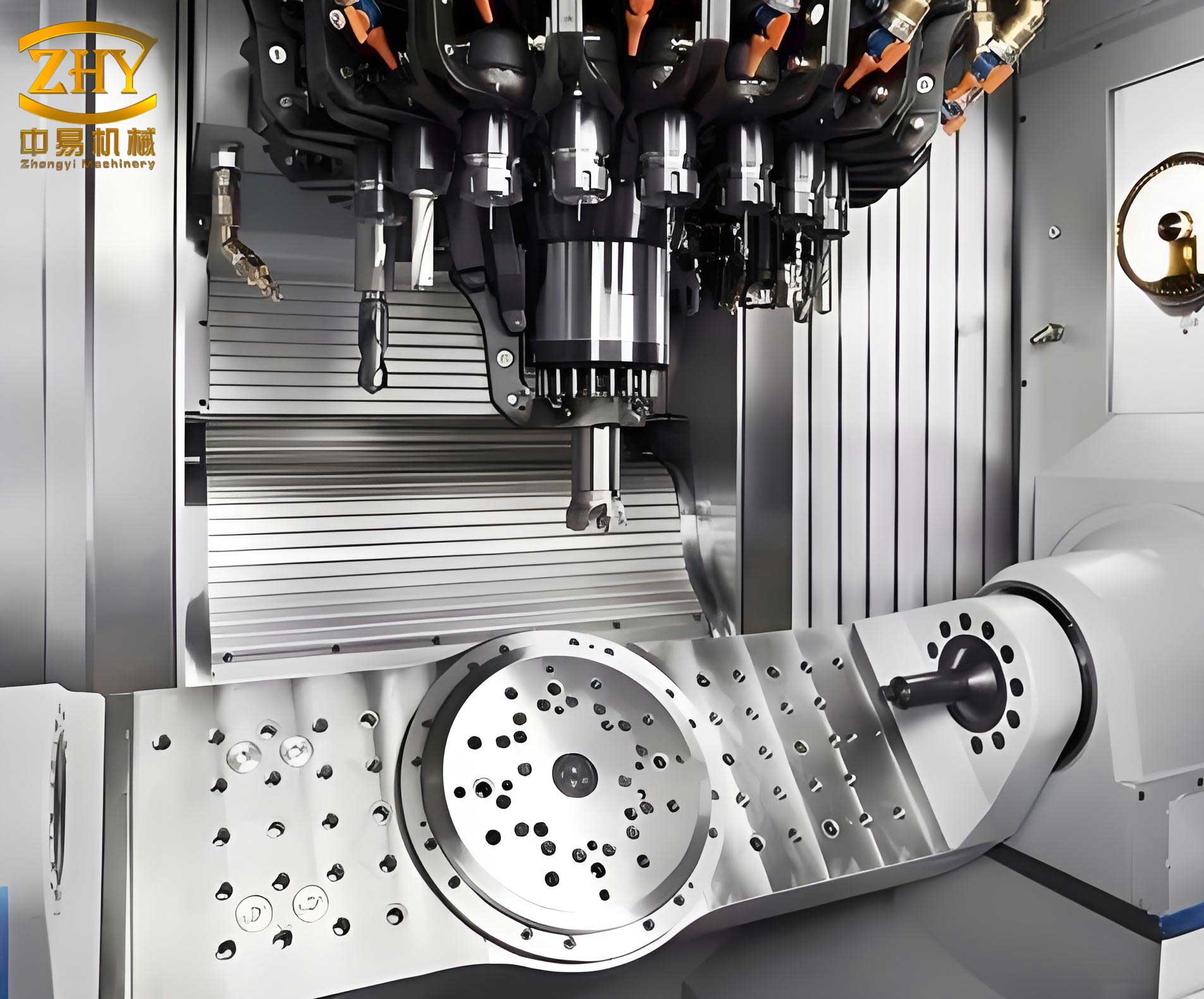
The production of high-integrity machine tool castings typically relies on sand casting methods. Traditional approaches often employ green sand or dry sand molds using split-box or multi-part molding techniques to manage complex geometries. Common gating systems include stepped (step-gate), bottom-gate, or combination styles. However, the universal application of a single method is a fallacy. The sensitivity of different casting structures to various process parameters varies significantly. What works for one bed structure may induce defects in another. Therefore, process design must be a bespoke activity, tailored to the specific geometry, material specifications, and production conditions. The following case studies exemplify this principle, focusing on how systematic analysis and targeted modifications resolved persistent quality issues in large machine tool castings.
The first case involves a large boring mill bed casting. This machine tool casting is massive, with an overall envelope dimension of approximately 5500 mm in length, 1200 mm in width, and 800 mm in height. The rough casting weight is near 12,000 kg. The material specification is gray iron, grade HT300, with a mandatory hardness requirement on the main guideways of 190-220 HB. The structure features a primary guideway flanked by auxiliary guideways on both sides, with the maximum thickness at the guide sections reaching 90 mm. The core quality requirement was the absolute soundness of the main and auxiliary guideway surfaces, as any subsurface defect would propagate during machining and impair the machine’s accuracy.
Our initial process design utilized a dry sand, split-box molding method. The gating system was an open-type, bottom-side gating arrangement. Molten iron was introduced from the横浇道 (runner) into the mold cavity from the lower outer sides of the two main guideways. To control the solidification of the thick guide sections, an array of graphite chills was placed on the main guideway surfaces. The design rationale was to ensure a smooth, non-turbulent fill from the bottom and promote directional solidification toward the risers. The fundamental solidification time for such a thick section can be estimated using Chvorinov’s rule:
$$ t_f = C_m \cdot \left( \frac{V}{A_s} \right)^2 $$
Where \( t_f \) is the total solidification time, \( V \) is the volume of the casting section, \( A_s \) is its surface area, and \( C_m \) is the mold constant specific to the sand material and conditions. For the thick guideway, controlling this time was crucial to prevent shrinkage porosity.
| Parameter | Value/Specification |
|---|---|
| Casting Type | Boring Mill Bed (Machine Tool Casting) |
| Material | Gray Iron HT300 |
| Weight (Rough) | ~12,000 kg |
| Critical Hardness | 190-220 HB (Main Guideways) |
| Initial Gating Design | Bottom-Side Gating (Open System) |
| Molding Method | Dry Sand, Split-Box |
| Chill Application | Graphite Chills on Main Guideways |
| Defect Observed (After 1st Trials) | Small Gas Holes & Slag Inclusions on Auxiliary Guideways |
| Defect on Main Guideways | None |
We produced three prototype castings using this initial design. Upon rough machining, the main guideways were perfectly sound. However, the auxiliary guideway surfaces exhibited scattered small gas holes and slag inclusions. This was a critical flaw for a precision machine tool casting. Our team conducted a thorough analysis of the filling pattern. In the bottom-side gating design, the metal enters at the base of the main guideway. As the molten iron level rises in the cavity, it must flow laterally to fill the auxiliary guideway sections. By the time the metal front reaches and turns into these areas, its temperature has dropped considerably due to heat loss to the mold walls. This lower-temperature metal has higher viscosity, reduced ability to assimilate entrapped gases, and diminished power to float slag particles to the top. Consequently, these imperfections became trapped just beneath the surface of the auxiliary guideways.
The solution was not to change the entire gating philosophy but to locally modify the thermal conditions at the point of metal entry into the auxiliary guideway region. We designed and implemented a “cold iron wash” or a small chill runner at the outer lower side of each auxiliary guideway. This was essentially a thin, wide channel (approx. 10mm x 100mm in cross-section) made of chill material. Its function was to act as a thermal sink for the first, cooler wave of metal entering that zone. This metal would quickly solidify in this sacrificial channel, preventing it from flowing into the critical guideway surface area. The subsequent, hotter metal would then fill the guideway properly. The modified layout proved successful, and the defect issue on the auxiliary guideways was resolved for subsequent prototype runs. This highlights a key principle in designing processes for machine tool castings: targeted thermal management is often more effective than wholesale system redesign.
However, when this “improved” process moved into batch production, a new and more severe problem emerged. On the main guideway surfaces, particularly on the face opposite the gating inlets, severe clusters of pin-hole gas porosity and slag inclusions appeared. This was perplexing, as these surfaces were defect-free during prototyping. Careful investigation of the actual as-poured castings and the gating passages after shakeout revealed anomalies. Some of the individual内浇口 (ingates) connecting the runner to the cavity were tilted significantly upward (instead of being perfectly horizontal), and some appeared discontinuous or “short-shot,” as if partially blocked during pouring.
This observation led to a revised hypothesis. The inconsistency in ingate angle and alignment, inevitable in manual or semi-manual molding in batch production, caused chaotic metal flow. Metal entering through a horizontally aligned ingate would flow forward, hit the far mold wall, and create a backflow. This reverse flow could force metal back into an upward-tilted neighboring ingate, where it would solidify and block that passage. Furthermore, during the initial turbulent stage of pouring, high-velocity metal jets could splash directly onto the main guideway surface through upward-pointing ingates, instantly freezing into “splash beads” that became nuclei for gas evolution and slag entrapment. The geometry of the guideway area also created a natural dead zone in the corner opposite the ingate, where slag and gases could accumulate without an efficient upward escape path. The flow dynamics can be partially modeled by considering the pressure loss at the ingate and the momentum of the stream. The initial velocity \( v \) of the metal stream can be related to the ferrostatic pressure head \( h \):
$$ v \approx \mu \sqrt{2gh} $$
where \( \mu \) is the discharge coefficient (affected by ingate shape and angle), \( g \) is gravity, and \( h \) is the effective head height. An upward-tilted ingate reduces the effective \( \mu \) for forward flow and increases the likelihood of splash and backflow.
The root cause was the directional nature of the bottom-side gating. To solve this, we fundamentally changed the metal introduction method for the main guideway section. We redesigned the gating to a true bottom-shower (or bottom-rain) style. In this design, multiple small, vertical ingates are arranged along the length of the guideway, directing metal streams upward directly into the previous dead zone area. This promotes a more uniform, multi-point fill from below, agitates the metal to help slag floatation, and eliminates the horizontal flow component that caused backflow and splash. The modification was a resounding success. The defect rate on the main guideways plummeted from an unacceptable level in batch production to below 2%. This case underscores that for deep-sectioned, critical surfaces in machine tool castings, a gating system that ensures direct, controlled, and non-turbulent metal entry is paramount. The evolution of the gating design for this boring mill bed is summarized below.
| Design Phase | Gating System Type | Metal Introduction Point | Key Issues | Corrective Action | Outcome |
|---|---|---|---|---|---|
| Initial Prototype | Bottom-Side Gating | Lower side of main guideways | Defects on auxiliary guideways | Added chill channels at auxiliary guideway inlets | Auxiliary guideway defects solved |
| Batch Production (Original Design) | Bottom-Side Gating | Lower side of main guideways (inconsistent ingate angles) | Severe gas/slag on main guideway faces | None (inherent flaw exposed) | High rejection rate |
| Final Optimized Design | Bottom-Shower (Rain) Gating | Multiple vertical points under main guideway dead zone | N/A | Redesigned entire ingate configuration | Defect rate <2%, stable production |
The second instructive case involves a guideway grinding machine frame, another quintessential large machine tool casting. Its dimensions were 4000 mm x 1000 mm x 1800 mm (LxWxH), with a weight of around 8000 kg. The distinguishing feature was the presence of upper and lower guideways on both vertical sides of the frame, resulting in a very high casting height of nearly 1800 mm. This height poses a significant challenge for achieving soundness in the vertical guideway surfaces, as the long travel path for slag and gas bubbles increases the risk of entrapment. While a higher pouring temperature can improve fluidity and slag floatation, it exacerbates the risk of shrinkage cavities in the heavy guideway sections. This trade-off is central to the process design for such tall machine tool castings.
Our initial analysis concluded that the upper sections of the side guideways, approximately at 60% of the total height, were particularly vulnerable due to poor conditions for slag and gas evacuation. Ideally, for best guideway quality, the gating should be located on the guideways themselves to ensure the hottest, cleanest metal reaches them first. However, this complicates mold construction and core assembly significantly. Our first process方案 adopted a double split-box molding method with two-end pouring using a stepped (step-gate) gating system with three levels for rapid filling. Additional measures included increasing machining allowance on the upper guideway top surfaces and placing slag and gas vent channels on the lower guideway top surfaces. Three trial castings produced with this method showed good quality, leading to its formal adoption for batch production.
Unfortunately, during batch production, a predictable defect pattern emerged: single large gas holes or slag pockets appeared on the top surfaces at the ends of the upper guideways on both sides. This indicated a systematic flaw related to the filling sequence and temperature gradient. The stepped gating from the ends created a filling pattern where the metal front advanced from both ends toward the center. At the far ends of the upper guideways, which were the last points to be filled by the upper-level gates, the metal temperature was likely at its lowest, and any accumulated slag or gas from the lower levels could be trapped there as the metal front met. The problem was linked to the location and direction of metal entry. The filling efficiency \( \eta_f \) of a gating system for a tall section can be conceptually related to the temperature drop \( \Delta T \) along the flow path \( L \):
$$ \Delta T \propto \frac{L \cdot \dot{q}}{v \cdot \rho \cdot C_p} $$
where \( \dot{q} \) is the heat flux to the mold, \( v \) is flow velocity, \( \rho \) is density, and \( C_p \) is specific heat. A long path \( L \) from the gate to the remote section leads to a large \( \Delta T \), compromising quality.
To address this, we reconfigured the gating system into a hybrid design: a combined bottom-shower and stepped gating system, but with a crucial change—the metal was now introduced from the side walls of the frame, not from the ends. The bottom-shower gates were placed along the side walls at lower levels to ensure a calm, upward fill of the massive sections, while the upper-step gates were also fed from the side. This created a more uniform temperature field along the length of the guideways and provided a direct, shorter path for slag and gas from the critical upper guideway ends to escape toward the central risers or vents. The modified process yielded consistently sound castings and stabilized production. This case demonstrates that for tall, complex machine tool castings with multiple critical surfaces, a composite gating strategy that carefully controls the metal entry points and filling sequence is often necessary to balance thermal needs and defect prevention.
| Aspect | Initial Design (Trial/Batch) | Optimized Design |
|---|---|---|
| Casting Type | Guideway Grinding Machine Frame (Machine Tool Casting) | |
| Molding Method | Double Split-Box | Double Split-Box |
| Gating System Concept | Two-End Pouring, Stepped (3-Level) | Side-Wall Pouring, Combined Bottom-Shower & Stepped |
| Metal Entry Direction | Longitudinal (from ends of casting) | Lateral (from side walls of casting) |
| Special Features | Increased allowance on upper guides; vent channels on lower guides | Retained vents; revised gate locations for direct filling of vulnerable zones |
| Primary Defect Observed | Large gas/slag at ends of upper guideways | None (significant reduction) |
| Process Stability | Unstable in batch production | Stable, high yield |
| Key Insight | End-gating creates cold spots and trap zones at remote guideway ends. | Side-gating with shower features ensures better thermal uniformity and shorter escape paths for impurities. |
Reflecting on these two detailed cases, several overarching principles for the process design of large, complex machine tool castings crystallize. First, there is no one-size-fits-all solution. Each machine tool casting must be analyzed individually, with a deep understanding of its geometric idiosyncrasies, thermal profiles, and critical quality zones. Second, the gating system is the circulatory system of the casting process; its design dictates the thermal history, flow dynamics, and ultimately, the internal soundness of the casting. Formulas like Chvorinov’s rule for solidification and fluid flow approximations provide a theoretical foundation, but practical validation through prototyping and careful production monitoring is indispensable.
Third, the transition from prototype to batch production often reveals hidden flaws related to process robustness and consistency. Factors like minor variations in core assembly, ingate formation, or sand properties can interact with a sensitive gating design to cause major defects. Therefore, the design must not only be effective but also forgiving of normal production variations. Fourth, composite or hybrid gating systems, such as the bottom-shower combined with side-feeding, offer powerful solutions for castings with conflicting requirements—like the need for bottom-up filling for temperature control and top feeding for slag floatation in tall sections.
The economic and quality imperative for getting the process right for machine tool castings cannot be overstated. The cost of a scrapped large bed or frame is enormous, not just in material but in lost production time and capacity. The iterative process of design, trial, analysis, and refinement, as shown, is a necessary investment. It requires a close collaboration between design engineering, foundry engineering, and production floor personnel. Advanced simulation software for mold filling and solidification is an invaluable tool today, but it must be calibrated and interpreted based on real-world foundry experience like the cases described.
In conclusion, the journey to perfect the process for a critical machine tool casting is one of applied science, empirical observation, and continuous improvement. The two instances discussed—the boring mill bed and the grinding machine frame—highlight that success lies in meticulous attention to detail: the angle of an ingate, the placement of a chill, the direction of metal flow. By respecting the unique character of each large machine tool casting and being willing to adapt and innovate the manufacturing process accordingly, foundries can achieve the levels of quality and reliability that the precision machinery industry demands. The pursuit of excellence in producing these foundational components continues to drive advancement in casting technology and metallurgical practice.