
In the pursuit of sustainable mobility and environmental stewardship, the automotive industry has increasingly focused on technologies that enhance efficiency and reduce emissions. As a researcher deeply involved in manufacturing processes, I have observed that turbochargers play a pivotal role in this endeavor, offering significant improvements in engine power, fuel economy, and emission control. Central to turbocharger performance is the quality of its housing components, particularly the shell castings. These shell castings, which form the structural backbone of turbochargers, must exhibit high precision, durability, and integrity to withstand demanding operational conditions. In this article, we delve into the intricacies of shell castings for turbocharger housings, analyzing existing processes, identifying defects, and proposing advanced solutions. Our goal is to foster a deeper understanding of shell castings, ensuring their reliability and promoting wider adoption in automotive applications.
Turbochargers, as forced induction systems, utilize exhaust gases to drive a turbine connected to a compressor, thereby increasing air intake density. This process enhances combustion efficiency, allowing smaller engines to produce more power while reducing fuel consumption and emissions. The shell castings, specifically the compressor and turbine housings, are critical components that encapsulate these mechanisms. They are typically manufactured through casting processes, which involve shaping molten alloy into complex geometries. The quality of these shell castings directly impacts turbocharger performance, making process optimization essential. We begin by exploring the fundamental aspects of turbochargers and the role of shell castings in their construction.
Structural Overview of Turbochargers and Shell Castings
A turbocharger comprises two primary sections: the compressor and the turbine, each housed within dedicated shell castings. The compressor side includes a centrifugal impeller, diffuser, and compressor housing, while the turbine side consists of a radial-flow turbine wheel, turbine housing, and associated components. Internally, a rotor supported by floating bearings manages axial forces via thrust bearings. Seal rings and oil deflectors are integrated to prevent leakage. The shell castings for these housings must accommodate intricate internal passages and withstand high temperatures and pressures. The manufacturing of these shell castings involves precise casting techniques to achieve the required mechanical properties and dimensional accuracy.
To illustrate the complexity, consider the thermal and mechanical loads on shell castings during operation. The turbine housing, for instance, is exposed to exhaust gases reaching temperatures above 800°C, necessitating materials with excellent heat resistance. Commonly, alloys such as austenitic stainless steels or nickel-based superalloys are used for turbine shell castings, while aluminum alloys are preferred for compressor housings due to their lightweight properties. The casting process for these shell castings must account for factors like thermal expansion, stress distribution, and fatigue resistance. We summarize key material properties for shell castings in Table 1.
| Material Type | Typical Alloy | Melting Point (°C) | Thermal Conductivity (W/m·K) | Application in Shell Castings |
|---|---|---|---|---|
| Aluminum Alloy | A356 | 600-650 | 150-180 | Compressor Housing |
| Stainless Steel | ACI HK30 | 1400-1450 | 15-20 | Turbine Housing |
| Nickel Alloy | Inconel 713C | 1300-1350 | 10-15 | High-Performance Turbine Shell Castings |
The design of shell castings also involves fluid dynamics considerations. For example, the compressor housing must optimize airflow with minimal losses, which can be modeled using Bernoulli’s principle for incompressible flow: $$ P_1 + \frac{1}{2} \rho v_1^2 = P_2 + \frac{1}{2} \rho v_2^2 $$ where \( P \) is pressure, \( \rho \) is density, and \( v \) is velocity. This equation highlights the importance of smooth internal surfaces in shell castings to reduce turbulence and improve efficiency.
Casting Process for Turbocharger Shell Castings
The production of turbocharger shell castings involves a multi-step casting process, meticulously controlled to ensure quality. As we examine this process, we emphasize the critical role of shell castings in determining final product performance. The primary stages include mold selection, preheating, pouring, and solidification. Each stage requires precise parameter management to avoid defects in the shell castings.
Initially, molds are selected based on the geometry of the shell castings. Sand casting or investment casting are commonly employed, depending on the alloy and complexity. For aluminum shell castings, permanent mold casting is often used to enhance dimensional stability. The mold preheating stage is crucial; we maintain temperatures around 300°C to prevent thermal shock and ensure uniform metal flow. This can be expressed through heat transfer principles: $$ Q = h A (T_m – T_0) $$ where \( Q \) is heat flux, \( h \) is the heat transfer coefficient, \( A \) is surface area, \( T_m \) is mold temperature, and \( T_0 \) is ambient temperature. Proper preheating minimizes thermal gradients in the shell castings, reducing residual stresses.
During pouring, molten alloy is introduced into the mold cavity. The pouring temperature and rate must be optimized to achieve a stable thermal equilibrium between the metal and mold. For aluminum shell castings, typical pouring temperatures range from 700°C to 750°C. We monitor this process using thermal analysis, where the cooling curve can be modeled as: $$ T(t) = T_p e^{-kt} $$ with \( T(t) \) as temperature at time \( t \), \( T_p \) as pouring temperature, and \( k \) as a cooling constant dependent on mold material and geometry. Controlled solidification is essential to prevent defects like shrinkage or porosity in the shell castings.
Core making is another vital aspect, especially for internal passages in shell castings. We inspect cores for integrity, ensuring no gas leaks or structural flaws. The use of bonded sand cores is common, and their properties affect the final quality of shell castings. After pouring, cooling rates are managed to achieve desired microstructures. For instance, rapid cooling can refine grain size in aluminum shell castings, enhancing strength according to the Hall-Petch equation: $$ \sigma_y = \sigma_0 + \frac{k_y}{\sqrt{d}} $$ where \( \sigma_y \) is yield strength, \( \sigma_0 \) is friction stress, \( k_y \) is a constant, and \( d \) is grain diameter.
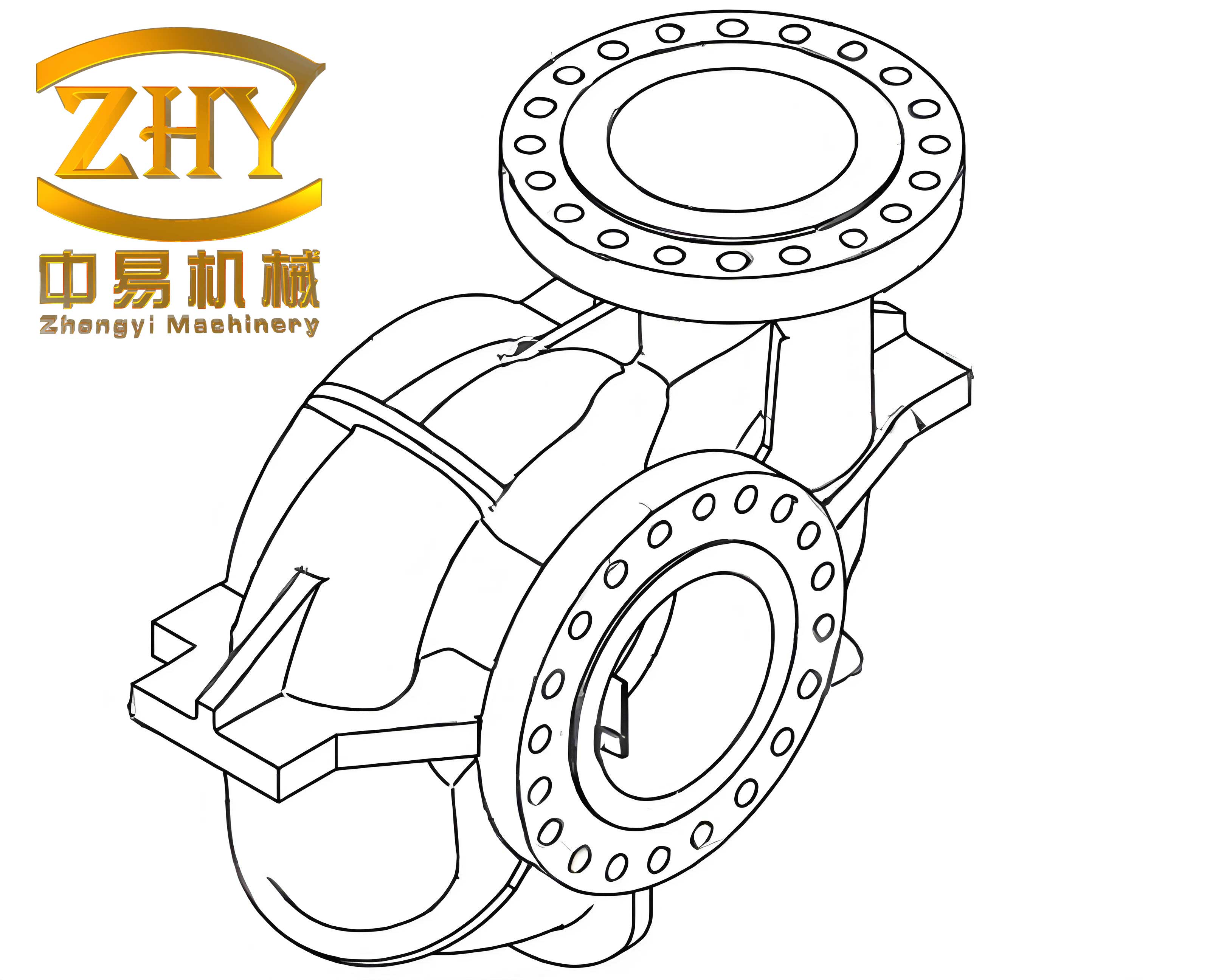
Melting and alloy preparation are equally important for shell castings. Aluminum alloys for compressor housings undergo melting, refining, and modification. We address issues like secondary contamination by pre-drying materials and tools. To prevent iron infiltration, tools are coated, and melt temperatures are controlled. The composition of shell castings is verified through spectral analysis, ensuring compliance with specifications. We summarize the melting parameters for aluminum shell castings in Table 2.
| Process Step | Temperature Range (°C) | Time (minutes) | Key Considerations |
|---|---|---|---|
| Melting | 720-760 | 30-60 | Avoid overheating to prevent gas absorption |
| Refining | 700-730 | 10-20 | Use argon or nitrogen for degassing |
| Modification | 710-740 | 5-10 | Add strontium or sodium for grain refinement |
| Pouring | 690-720 | N/A | Maintain steady flow to minimize turbulence |
Defect Analysis in Shell Castings
Despite advancements, defects in turbocharger shell castings remain a challenge, affecting performance and cost. We have identified common issues through industrial observations and research. The primary defects in shell castings include flash formation, porosity, shrinkage cavities, and dimensional inaccuracies. These defects not only compromise the integrity of shell castings but also increase machining time and material waste.
Flash, or excess material along mold parting lines, occurs due to mold wear or improper clamping. In shell castings, flash leads to additional finishing operations, raising production costs. Porosity, caused by gas entrapment or inadequate venting, weakens the structure and can cause leakage under pressure. Shrinkage defects result from improper solidification patterns, often localized in thick sections or “hot spots.” We analyze these defects using quality metrics, such as defect density per unit volume in shell castings: $$ D_d = \frac{N_d}{V_c} $$ where \( D_d \) is defect density, \( N_d \) is number of defects, and \( V_c \) is volume of the casting.
Thermal analysis reveals that hot spots in shell castings disrupt uniform cooling, leading to shrinkage. The temperature distribution can be modeled with Fourier’s law: $$ \nabla \cdot (k \nabla T) = \rho c_p \frac{\partial T}{\partial t} $$ where \( k \) is thermal conductivity, \( T \) is temperature, \( \rho \) is density, and \( c_p \) is specific heat. Solving this equation for complex geometries of shell castings helps identify regions prone to defects. We illustrate common defect locations in shell castings through simulation studies, emphasizing the need for process optimization.
Moreover, wall thickness variations in shell castings contribute to defects. Thicker sections cool slower, creating thermal stresses that may cause cracking or distortion. We quantify this using the modulus of rigidity and thermal strain: $$ \epsilon = \alpha \Delta T $$ where \( \epsilon \) is strain, \( \alpha \) is coefficient of thermal expansion, and \( \Delta T \) is temperature difference. Controlling wall thickness uniformity in shell castings is crucial for minimizing residual stresses.
To summarize defect types and causes in shell castings, we present Table 3, based on empirical data from manufacturing trials.
| Defect Type | Primary Cause | Impact on Shell Castings | Detection Method |
|---|---|---|---|
| Flash | Mold misalignment or wear | Increases machining effort, reduces aesthetics | Visual inspection, dimensional checks |
| Porosity | Gas entrapment during pouring | Reduces mechanical strength, may cause leaks | X-ray imaging, ultrasonic testing |
| Shrinkage Cavities | Inadequate feeding or hot spots | Creates voids, lowers fatigue resistance | Thermal analysis, sectioning |
| Dimensional Inaccuracy | Mold deformation or thermal expansion | Affects assembly and performance | Coordinate measuring machines (CMM) |
Improvement Strategies for Shell Castings
To enhance the quality of turbocharger shell castings, we propose several advanced techniques focused on thermal management and process control. These strategies aim to mitigate defects and improve the consistency of shell castings. By addressing hot spots and optimizing solidification, we can achieve superior shell castings with minimal rework.
First, cooling methods play a key role in regulating temperatures during casting. Water cooling involves embedding channels in molds to extract heat rapidly. For shell castings with complex internal features, this method reduces solidification time but adds design complexity. The heat removal rate can be calculated as: $$ \dot{Q} = \dot{m} c_p (T_{out} – T_{in}) $$ where \( \dot{Q} \) is heat removal rate, \( \dot{m} \) is water mass flow rate, and \( T_{out} \) and \( T_{in} \) are outlet and inlet temperatures. Alternatively, air cooling uses compressed air for localized cooling in shell castings, offering simplicity but lower efficiency.
Second, indirect cooling techniques, such as chill inserts or cold irons, are effective for hot spots in shell castings. These high-conductivity materials accelerate cooling in specific regions, promoting directional solidification. We can model their effect using thermal resistance networks: $$ R_{th} = \frac{L}{kA} $$ where \( R_{th} \) is thermal resistance, \( L \) is thickness, \( k \) is conductivity, and \( A \) is area. By strategically placing chills, we control the solidification sequence in shell castings, reducing shrinkage defects.
Third, mold cavity modification is a proactive approach. By adjusting the geometry of shell castings within machining allowances, we minimize thick sections that cause hot spots. This involves computational fluid dynamics (CFD) and finite element analysis (FEA) to simulate flow and thermal patterns. For example, redesigning ribs or bosses in shell castings can enhance heat dissipation. We often use topology optimization algorithms to achieve lightweight yet robust shell castings.
Fourth, thermal insulation methods, like exothermic sleeves or insulating coatings, slow down cooling in feeding systems. This ensures adequate metal supply to compensate for shrinkage in shell castings. The effectiveness can be evaluated through the Niyama criterion for porosity prediction: $$ N_y = \frac{G}{\sqrt{\dot{T}}} $$ where \( G \) is temperature gradient and \( \dot{T} \) is cooling rate. Maintaining a high Niyama value in shell castings reduces porosity risk.
Fifth, advanced technologies like heat pipes offer efficient heat transfer with minimal temperature gradients. Based on phase-change principles, heat pipes redistribute heat within molds for shell castings, improving uniformity. Their performance is governed by: $$ Q_{hp} = \frac{\Delta T}{R_{hp}} $$ where \( Q_{hp} \) is heat transfer rate and \( R_{hp} \) is thermal resistance of the heat pipe. Integrating heat pipes into mold designs for shell castings can stabilize thermal profiles.
Lastly, implementing mold temperature control systems allows precise regulation of cavity temperatures. Using multi-zone heaters or coolers, we can manage regional temperatures in shell castings production. This is expressed via PID control algorithms: $$ u(t) = K_p e(t) + K_i \int e(t) dt + K_d \frac{de}{dt} $$ where \( u(t) \) is control output, \( e(t) \) is error, and \( K_p, K_i, K_d \) are constants. Such systems enhance repeatability in manufacturing shell castings.
We compare these improvement methods for shell castings in Table 4, highlighting their applications and benefits.
| Method | Mechanism | Advantages for Shell Castings | Limitations |
|---|---|---|---|
| Water Cooling | Convective heat transfer through channels | Rapid cooling, reduces cycle time | Complex mold design, risk of leaks |
| Air Cooling | Forced convection with compressed air | Simple implementation, flexible | Lower efficiency, noise |
| Chill Inserts | Conductive cooling using high-k materials | Targeted cooling, improves solidification | Additional cost, may cause stress concentrations |
| Mold Redesign | Geometric optimization to avoid hot spots | Prevents defects at source, enhances performance | Requires simulation expertise, may affect function |
| Thermal Insulation | Reduces heat loss in feeding systems | Better feeding, minimizes shrinkage | Material cost, may increase cycle time |
| Heat Pipes | Phase-change heat transfer | High efficiency, uniform temperature | Expensive, integration challenges |
| Temperature Control Systems | Active regulation with sensors and actuators | Precise control, adaptable to variations | High initial investment, maintenance needed |
Additionally, process parameters optimization is vital for shell castings. We employ statistical methods like Design of Experiments (DoE) to identify optimal settings for pouring temperature, mold temperature, and cooling rate. Regression models can predict defect probability in shell castings: $$ P_{defect} = \beta_0 + \beta_1 T_p + \beta_2 T_m + \beta_3 t_c $$ where \( P_{defect} \) is defect probability, \( \beta \) coefficients are determined experimentally, \( T_p \) is pouring temperature, \( T_m \) is mold temperature, and \( t_c \) is cooling time. By minimizing \( P_{defect} \), we enhance the yield of high-quality shell castings.
Future Directions and Conclusion
In summary, the manufacturing of turbocharger shell castings is a sophisticated process that demands continuous innovation. Through this analysis, we have underscored the importance of shell castings in achieving automotive sustainability goals. By addressing defects via advanced cooling techniques, mold modifications, and process control, we can significantly improve the quality and reliability of shell castings.
Looking ahead, emerging trends such as additive manufacturing for mold making, real-time monitoring with IoT sensors, and AI-driven process optimization hold promise for shell castings. These technologies could enable customized shell castings with reduced lead times and enhanced performance. Furthermore, material advancements, like composite alloys or ceramic reinforcements, may offer superior properties for shell castings operating under extreme conditions.
We conclude that a holistic approach, integrating simulation, experimentation, and smart manufacturing, is essential for advancing shell castings. As the automotive industry evolves towards electrification and hybrid systems, turbochargers with optimized shell castings will remain crucial for efficient internal combustion engines. By refining these processes, we contribute to broader environmental objectives, such as reducing emissions and improving fuel economy. Ultimately, the relentless pursuit of excellence in shell castings will drive progress in automotive engineering and beyond.