
The production of high-integrity, complex thin-walled shell castings, such as torque converter housings for forklift trucks, presents a significant challenge in foundry engineering. Traditionally, these components were manufactured using resin sand casting processes. While functional, this method involved extensive core-making, core assembly, and molding operations, leading to complexities, reduced production efficiency, and inherent quality issues like dimensional inaccuracies and excessive flash. The transition to Lost Foam Casting (LFC) represents a paradigm shift towards near-net-shape manufacturing for such intricate shell castings. This article details a first-person, comprehensive analysis of the process development, simulation, and implementation for producing these critical shell castings, leveraging extensive data, formulas, and technical insights.
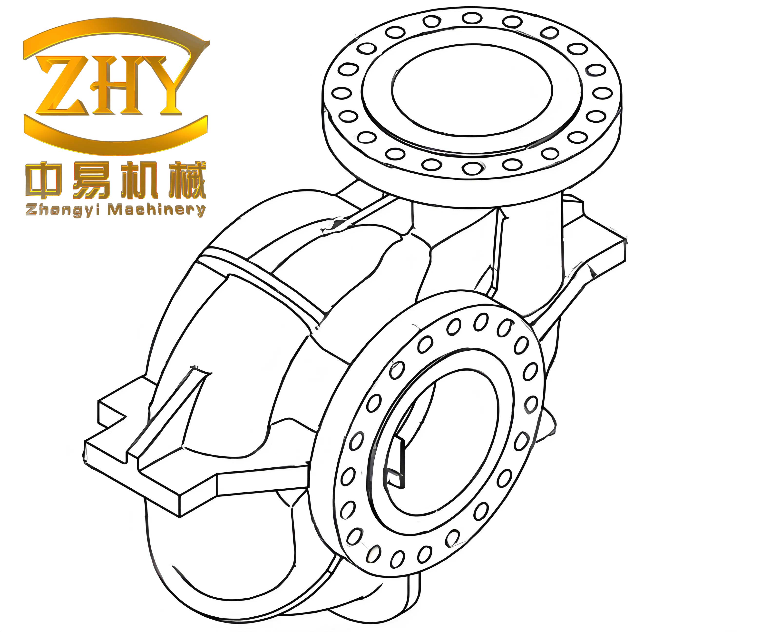
The torque converter housing is a quintessential example of a complex thin-walled shell casting. Its geometry features a circular open-box structure with an average wall thickness of approximately 8 mm, a thin-shelled bell mouth opening, side ports with recessed areas, and a large machined base plane. This combination makes it prone to distortion, filling defects in remote sections, and shrinkage porosity in thicker junctions. The primary technical objectives were to eliminate distortion in the critical bell mouth, ensure internal soundness free from shrinkage defects, and achieve a superior as-cast surface finish to minimize machining allowance.
The core advantage of Lost Foam Casting for these shell castings lies in the decomposition of complexity. Instead of dealing with complex cores and molds, the complexity is transferred to the foam pattern. For the torque converter housing, the strategy involved segmenting the overall pattern into manufacturable sections. A typical segmentation includes: the Base Section (containing the major mounting plane and internal channels), the Middle Body Section (forming the cylindrical walls and side ports), and the Top Bell Mouth Section. Each segment is individually molded using expanded polystyrene (EPS) or copolymer beads in precision-aluminum dies. The critical process parameters for foam molding—steam pressure, temperature, time, and cooling cycle—are meticulously controlled to achieve a pattern with high dimensional fidelity, minimal bead fusion lines, and low density to reduce pyrolysis products during casting.
The key challenges and our corresponding engineering solutions for these shell castings are summarized below:
| Challenge | Root Cause | Engineered Solution in LFC Process | Outcome |
|---|---|---|---|
| Bell Mouth Distortion | Non-uniform thermal contraction (vertical vs. horizontal) during solidification in vertical pouring. | Adoption of horizontal pouring orientation. Design of a stabilized gating system to support the pattern. | Uniform contraction in all directions, maintaining circularity. |
| Pattern Collapse/Lift | Buoyancy forces from liquid metal exceeding the uniaxial strength of the compacted sand bed. | Increased sprue diameter to enhance filling rate and metal pressure. Optimization of sand compaction, especially around the pattern. | Minimized pattern deformation, ensuring dimensional accuracy. |
| Burn-on/Penetration | Insufficient or non-uniform coating barrier at intricate internal corners and recesses. | Implementation of a dual-coating process: primary dip coating followed by a secondary spray or brush coating on critical internal areas. | Effective isolation of foam pyrolysis products, yielding a clean casting surface. |
| Cold Shuts/Incomplete Filling | Premature degradation of foam in isolated, thin-section cavities, causing gas pressure buildup. | Strategic placement of small foam overflow risers connected to remote oil galleries and thin sections. Optimization of pouring temperature and vacuum level. | Complete cavity fill without surface defects like folds or mistruns. |
| Dimensional Accuracy of Pattern | Cumulative errors from foam shrinkage, segment gluing, and handling. | Pre-calculation and compensation of foam shrinkage in mold design. Use of high-precision, low-shrinkage glues and jigs for assembly. Post-assembly trimming and verification. | Pattern dimensions within CT5-6 range, enabling net-shape casting. |
The initial trials utilized a vertical gating system, pouring metal from the base. The solidification dynamics in this orientation proved detrimental for the bell mouth. The differential cooling and constraint led to predictable ovalization, expressed empirically by a distortion factor $\delta$:
$$ \delta = \alpha \cdot \Delta T \cdot L \cdot (1 – \nu) $$
where $\alpha$ is the thermal contraction coefficient of the alloy, $\Delta T$ is the temperature drop through the solidus, $L$ is the characteristic dimension, and $\nu$ is the Poisson’s ratio. In vertical pouring, the constraint varies with height, making $\delta$ non-uniform across the circumference. Switching to a horizontal pouring scheme, as illustrated in the process layout, was transformative. In this configuration, the bell mouth lies in a horizontal plane, and the thermal gradient and constraints during solidification become more axisymmetric, effectively minimizing $\delta$ and preserving geometry. The gating system was redesigned with a larger cross-sectional area sprue to increase the metallostatic head and filling velocity $v_f$, calculated to overcome the gas back-pressure $P_g$ from foam degradation:
$$ v_f \geq \sqrt{\frac{2(P_m + \rho g h – P_g)}{\rho}} $$
where $P_m$ is the vacuum pressure in the mold, $\rho$ is the metal density, $g$ is gravity, and $h$ is the effective sprue height.
A critical quality enabler is the refractory coating. For these thin-walled shell castings, the coating must have excellent permeability to allow rapid gas evacuation but sufficient strength and refractoriness to resist metal penetration. The dual-coating approach was vital. The primary dip coating ensures a uniform base layer. The secondary manual spray/brush coating targets internal fillets, corners of side ports, and the roof of internal passages within the shell casting—areas where dip coating may drain or bubble, leaving weak spots. The coating thickness $t_c$ is controlled within 0.3-0.5 mm, balancing insulation and permeability. Its effectiveness in preventing burn-on is related to its hot strength and the gas permeability $k$, which must be high enough to satisfy the condition for defect-free casting:
$$ k > \frac{\mu \cdot \dot{m}_g \cdot L_g}{A \cdot (P_i – P_m)} $$
Here, $\mu$ is the gas viscosity, $\dot{m}_g$ is the mass rate of gas generation from the foam, $L_g$ is the coating thickness, $A$ is the area, and $P_i$ is the interfacial pressure at the metal-coating front.
To de-risk the process and optimize parameters before physical trials, numerical simulation software was employed extensively. The simulation solves the coupled equations for fluid flow, heat transfer, and foam degradation within the porous sand medium. The key governing equations for the filling stage include a modified Navier-Stokes equation incorporating the Darcy term for flow in a porous medium:
$$ \rho \left( \frac{\partial \vec{v}}{\partial t} + (\vec{v} \cdot \nabla)\vec{v} \right) = -\nabla P + \mu \nabla^2 \vec{v} – \frac{\mu}{K} \vec{v} + \rho \vec{g} $$
where $K$ is the sand permeability. The energy equation accounts for the heat absorption due to foam pyrolysis:
$$ \rho C_p \frac{\partial T}{\partial t} + \rho C_p (\vec{v} \cdot \nabla)T = \nabla \cdot (k \nabla T) – \dot{Q}_{pyrolysis} $$
The simulation outputs, such as temperature contours, fill sequences, and velocity vectors, were instrumental in identifying potential cold shut areas (leading to the addition of overflow risers) and visualizing the solidification sequence to assess shrinkage risk. By iteratively modifying the gating design in-silico, an optimal layout was achieved that promoted progressive solidification from the extremities of the shell casting back toward the feeder gates.
The metallurgical quality of the final shell castings is paramount. The base material is typically a ductile iron (e.g., EN-GJS-400-18 or equivalent). Melting is conducted in a medium-frequency induction furnace, allowing precise control over temperature and chemistry. Inoculation and nodularization treatments are performed in-pour to ensure a high nodule count and avoid chill in the thin walls. The carbon equivalent (CE) is tightly controlled to favor a eutectic composition, promoting fluidity for thin-wall filling and reducing shrinkage tendency:
$$ CE = \%C + \frac{1}{3}(\%Si + \%P) $$
A target CE between 4.3 and 4.5 is typical. The following table outlines the controlled chemistry range and achieved mechanical properties for the shell castings:
| Element/Property | Target Range | Typical Achieved Value |
|---|---|---|
| Carbon (C) | 3.5 – 3.8% | 3.65% |
| Silicon (Si) | 2.2 – 2.6% | 2.4% |
| Manganese (Mn) | < 0.3% | 0.2% |
| Magnesium (Mg) | 0.03 – 0.05% | 0.04% |
| Carbon Equivalent (CE) | 4.3 – 4.5 | 4.45 |
| Tensile Strength | > 400 MPa | 420-450 MPa |
| Elongation | > 18% | 20-22% |
| Nodule Count | > 120 nodules/mm² | 140-160 nodules/mm² |
The implementation of this optimized Lost Foam Casting process has yielded exceptional results for the torque converter shell castings. The dimensional consistency achieved is remarkable, with casting dimensional tolerances consistently meeting CT6 to CT7 grades as per ISO 8062. The surface finish, measured directly on the as-cast parts, ranges from Ra 6.3 to 12.5 µm. This superior surface quality and dimensional precision directly translate to a significant reduction in machining allowance, classified as MA-F grade. The comprehensive scrap rate for these shell castings, including all foundry and cleaning defects, has been maintained below 1% in steady-state production.
The economic and operational benefits are substantial. A direct comparison with the former resin sand process reveals decisive advantages. The elimination of core shops, core binders, and complex mold assembly drastically simplifies the production flow. The sand, being unbonded, is 100% reclaimable with minimal processing. The following table quantifies the key performance indicators contrasting the two processes for manufacturing these shell castings:
| Performance Indicator | Resin Sand Casting | Lost Foam Casting |
|---|---|---|
| Process Steps for Mold/Core | Core Making, Core Baking, Core Assembly, Molding | Pattern Assembly, Coating, Sand Compaction |
| Dimensional Accuracy (CT Grade) | CT8 – CT10 | CT6 – CT7 |
| Typical Surface Roughness (Ra) | 25 – 50 µm | 6.3 – 12.5 µm |
| Machining Allowance | Significant, variable | Minimal, consistent (MA-F) |
| Sand Reclamation Rate | < 80% (with treatment) | > 99% (simple screening) |
| Relative Production Cycle Time | 1.0 (Baseline) | ~0.7 |
The culmination of this technical development is a robust, repeatable, and economically superior manufacturing process for complex thin-walled shell castings. The Lost Foam Casting methodology, through strategic pattern segmentation, optimized horizontal gating, controlled dual-coating applications, and physics-based simulation, has successfully overcome the historical challenges of distortion, shrinkage, and surface defects. The resulting shell castings exhibit high dimensional precision, excellent metallurgical properties, and a superior surface finish. This translates not only into a direct reduction in component cost—on the order of a significant cost saving per ton of castings—but also into enhanced performance and reliability in the final application. The success with the torque converter housing establishes a proven framework for applying Lost Foam Casting to a broader family of intricate, thin-walled shell castings across various industries.