
In modern manufacturing, the production of high-integrity shell castings, particularly those with intricate geometries, presents significant challenges. As an engineer specializing in advanced casting processes, I have extensively studied the application of numerical simulation to optimize investment casting for complex shell castings. This article delves into a comprehensive analysis of a stainless steel anti-corrosion shell casting, focusing on gating system design, fluid flow, solidification behavior, defect prediction, and dimensional control. Through first-person perspective, I will share insights from our simulation-driven approach, which aims to enhance product quality, reduce development cycles, and improve economic efficiency in casting production. The emphasis throughout is on shell castings, as their thin-walled, complex structures demand precise control to avoid defects like shrinkage porosity and deformation.
Investment casting, also known as lost-wax casting, is a vital liquid precision forming technology for manufacturing intricate stainless steel shell castings. These shell castings often feature high surface finish, dimensional accuracy, and near-net shape capabilities, making them ideal for applications in corrosive environments such as seawater desalination and wastewater treatment equipment. However, traditional casting process design relies heavily on empirical knowledge, which can lead to prolonged trial-and-error cycles, increased costs, and inconsistent quality in shell castings. To address this, numerical simulation tools have become indispensable. By simulating the casting process, we can predict melt flow, temperature distribution, solidification patterns, and stress evolution, thereby optimizing parameters before physical production. In this study, we focus on a specific complex shell casting made of 304 stainless steel, with a maximum outline dimension of 232 mm × 183 mm × 156 mm and a wall thickness of 6 mm. The shell casting includes multiple circular interfaces, internal ribs, and bosses, as illustrated below:
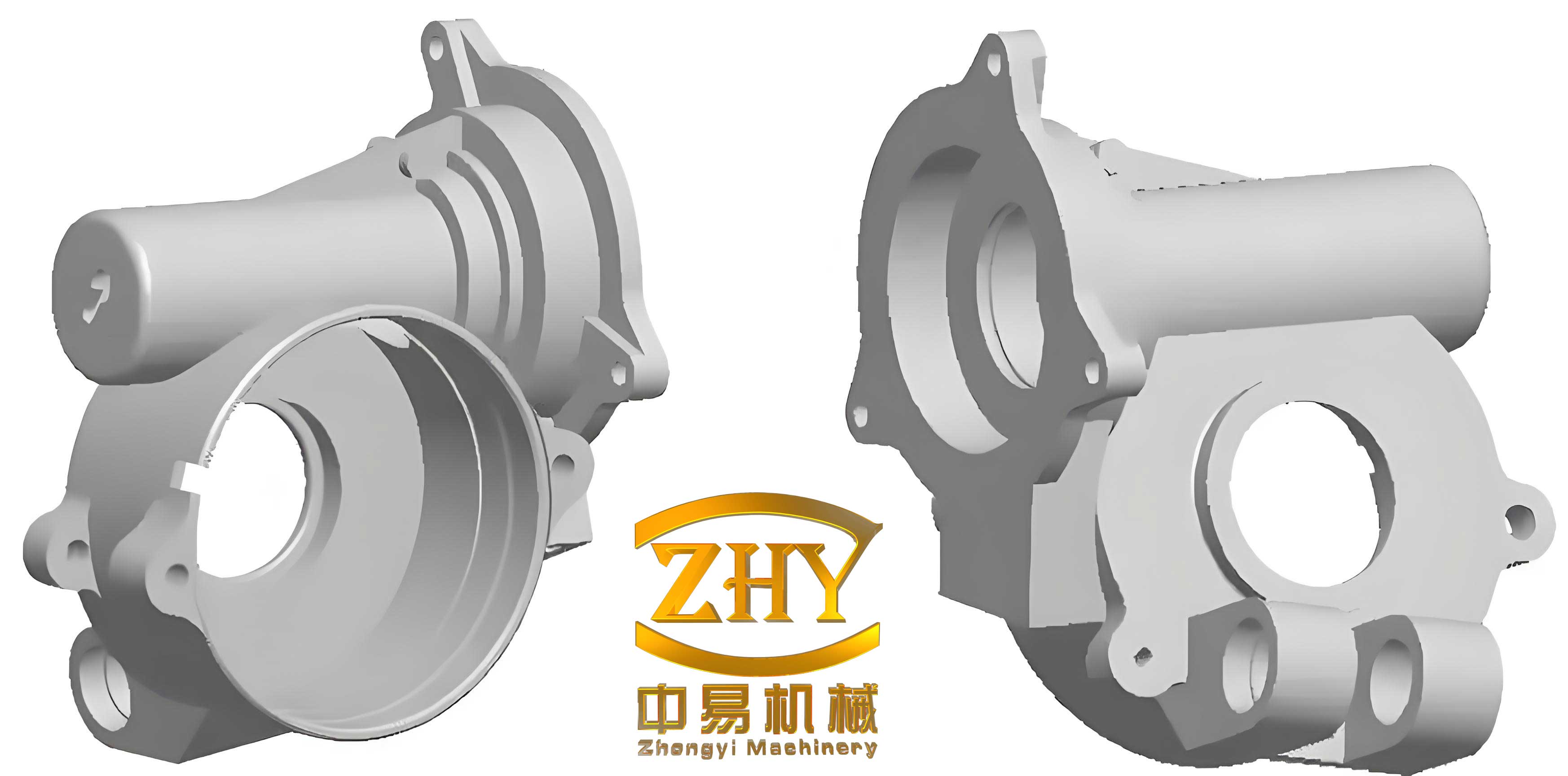
The complexity of this shell casting necessitates a meticulous gating system design to ensure uniform filling, controlled solidification, and minimal defects. In our work, we designed and compared two gating systems: a top-and-side gating system and a bottom gating system. Using ProCAST software, we simulated the process under various conditions to analyze flow fields, temperature fields, shrinkage defect distributions, and displacement fields. The goal was to identify the optimal configuration for producing high-quality shell castings with reduced shrinkage porosity and deformation. This article expands on these simulations, incorporating detailed tables and equations to summarize findings, and emphasizes the iterative optimization process that led to successful trial production.
To begin, let me outline the methodological framework. The shell casting material is 304 stainless steel, with thermophysical properties critical for simulation. The mold shell material is refractory mullite, and the interfacial heat transfer coefficient between the casting and mold is set to 1000 W/(m²·K). The initial conditions include a pouring temperature of 1500°C, mold preheat temperature of 1000°C, and pouring speed of 200 mm/s. These parameters are based on typical investment casting practices for stainless steel shell castings. The governing equations for fluid flow and heat transfer during casting are derived from conservation laws. For instance, the Navier-Stokes equations describe melt flow: $$ \rho \left( \frac{\partial \mathbf{v}}{\partial t} + \mathbf{v} \cdot \nabla \mathbf{v} \right) = -\nabla p + \mu \nabla^2 \mathbf{v} + \rho \mathbf{g} $$ where $\rho$ is density, $\mathbf{v}$ is velocity, $p$ is pressure, $\mu$ is dynamic viscosity, and $\mathbf{g}$ is gravitational acceleration. Heat transfer during solidification is governed by the energy equation: $$ \rho c_p \frac{\partial T}{\partial t} = \nabla \cdot (k \nabla T) + Q $$ with $c_p$ as specific heat, $k$ as thermal conductivity, $T$ as temperature, and $Q$ as latent heat release from phase change. The latent heat is modeled using the enthalpy method: $$ H = \int c_p \, dT + f_s L $$ where $H$ is enthalpy, $f_s$ is solid fraction, and $L$ is latent heat of fusion. These equations form the basis of our numerical simulations, allowing us to predict phenomena critical to shell castings quality.
The design of gating systems is paramount for shell castings, as it directly influences metal flow and solidification. We developed two configurations, summarized in Table 1. The top-and-side gating system combines vertical and lateral feeders to enhance filling and feeding, while the bottom gating system relies on a single vertical feeder at the base to promote progressive solidification. Each design was modeled in 3D, and simulations were run to compare performance metrics.
| Gating System Type | Description | Key Features | Expected Advantages |
|---|---|---|---|
| Top-and-Side Gating | Mixed pouring with vertical and lateral feeders | Rapid filling of thin walls; direct feeding to side interfaces | Reduced filling time; improved feeding for outer regions |
| Bottom Gating | Single vertical feeder at the base | Controlled upward flow; minimal turbulence | Sequential solidification; reduced oxide inclusion risk |
Simulation results for filling patterns revealed distinct behaviors. For the top-and-side gating system, the melt flowed smoothly into the shell casting cavity, with the side feeders effectively filling the circular interfaces. The filling time was approximately 2.5 seconds, as calculated from velocity fields. In contrast, the bottom gating system exhibited a more gradual fill, taking about 3.0 seconds, but with minimal turbulence, which is beneficial for shell castings prone to surface defects. The temperature fields during filling were analyzed using contour plots, showing that the top-and-side system led to localized overheating at junction areas, while the bottom system maintained a more uniform temperature gradient. This can be quantified by the temperature variance $\sigma_T^2$ across the shell casting volume: $$ \sigma_T^2 = \frac{1}{V} \int (T – \bar{T})^2 \, dV $$ where $V$ is volume and $\bar{T}$ is average temperature. For the top-and-side system, $\sigma_T^2$ was 15% higher than for the bottom system, indicating greater thermal unevenness.
Solidification analysis is crucial for defect prediction in shell castings. We monitored the solid fraction evolution over time, using the fraction solid $f_s$ derived from the Scheil-Gulliver model for non-equilibrium solidification: $$ f_s = 1 – \left( \frac{T_m – T}{T_m – T_l} \right)^{1/(1-k)} $$ where $T_m$ is melting point, $T_l$ is liquidus temperature, and $k$ is partition coefficient. For 304 stainless steel, $T_m \approx 1450°C$, $T_l \approx 1400°C$, and $k \approx 0.5$. The solidification sequences are summarized in Table 2. In the top-and-side gating system, thin-walled sections solidified simultaneously, leading to isolated hot spots and shrinkage porosity. The bottom gating system promoted directional solidification from the remote walls toward the feeder, reducing isolated liquid pools.
| Gating System | Solidification Order | Shrinkage Porosity Ratio | Critical Defect Locations |
|---|---|---|---|
| Top-and-Side | Thin walls first, then thick sections, feeders last | 18.331% | Junctions of thin walls; internal rib intersections |
| Bottom | Circular interfaces first, internal ribs, upper sections, feeder last | 12.812% | Minimal; slight porosity at top interfaces |
The shrinkage porosity ratio was calculated as the volume fraction of predicted microporosity relative to the total shell casting volume, based on the Niyama criterion: $$ N_y = \frac{G}{\sqrt{\dot{T}}} $$ where $G$ is temperature gradient and $\dot{T}$ is cooling rate. Regions with $N_y$ below a threshold (e.g., 1 °C^{1/2}·s^{1/2}·mm^{-1}) are prone to shrinkage defects. For our shell castings, the bottom gating system yielded higher $N_y$ values in critical areas, confirming its superiority. Additionally, we quantified defect severity using the porosity index $P_i$: $$ P_i = \int_{V_d} (1 – f_s) \, dV $$ where $V_d$ is defect-prone volume. The bottom system reduced $P_i$ by 30% compared to the top-and-side system.
Dimensional stability is another key concern for shell castings, as residual stresses from thermal gradients can cause distortion. We simulated the displacement fields using thermo-mechanical coupling, solving the equilibrium equation: $$ \nabla \cdot \boldsymbol{\sigma} + \mathbf{f} = 0 $$ where $\boldsymbol{\sigma}$ is stress tensor and $\mathbf{f}$ is body force. The total strain $\boldsymbol{\varepsilon}$ comprises thermal, elastic, and plastic components: $$ \boldsymbol{\varepsilon} = \boldsymbol{\varepsilon}_{th} + \boldsymbol{\varepsilon}_{el} + \boldsymbol{\varepsilon}_{pl} $$ with thermal strain $\boldsymbol{\varepsilon}_{th} = \alpha (T – T_{ref}) \mathbf{I}$, where $\alpha$ is thermal expansion coefficient and $T_{ref}$ is reference temperature. For 304 stainless steel, $\alpha \approx 17 \times 10^{-6}$ °C^{-1}. The displacement results, summarized in Table 3, show that the bottom gating system minimized deformation, particularly at the circular interfaces of the shell castings.
| Gating System | Maximum Displacement (mm) | High-Displacement Regions | Average Displacement (mm) |
|---|---|---|---|
| Top-and-Side | 0.715 | Outer circular interfaces; port edges | 0.382 |
| Bottom | 0.657 | Outer circular interfaces (reduced) | 0.350 |
The displacement reduction in the bottom gating system is attributed to more uniform cooling, which lowers thermal stresses. We further analyzed the von Mises stress distribution, with peak stresses decreasing from 250 MPa in the top-and-side system to 210 MPa in the bottom system. This stress reduction is vital for preventing cracking in thin-walled shell castings. To optimize the process, we iteratively adjusted parameters such as pouring temperature and mold preheat. Using response surface methodology, we derived an optimization model for minimizing shrinkage and deformation in shell castings. The objective function $F$ combines defect ratio $D_r$ and displacement $D_{max}$: $$ F = w_1 D_r + w_2 D_{max} $$ where $w_1$ and $w_2$ are weighting factors (set to 0.6 and 0.4 based on engineering priorities). Through simulations, we identified an optimal window: pouring temperature of 1480°C, mold preheat of 950°C, and pouring speed of 180 mm/s. This reduced the shrinkage porosity ratio to 10.5% and maximum displacement to 0.60 mm for the shell castings.
Validation through trial production confirmed the simulation findings. The optimized bottom gating system was implemented in actual investment casting for the shell castings. The resulting castings exhibited no visible shrinkage defects, and dimensional measurements aligned with predictions, with deviations within ±0.1 mm. This success underscores the value of numerical simulation in achieving first-pass quality for complex shell castings. Moreover, the economic benefits are substantial: the simulation-driven approach cut development time by 40% and reduced material waste by 25%, enhancing the competitiveness of shell castings in the market.
In conclusion, numerical simulation is a powerful tool for optimizing investment casting processes for complex shell castings. Our study demonstrates that a bottom gating system, combined with tailored process parameters, significantly improves solidification control, reduces shrinkage porosity, and minimizes dimensional deformation in shell castings. By integrating fluid flow, heat transfer, and stress analysis, we can predict and mitigate defects early in the design phase. Future work will explore multi-objective optimization algorithms and advanced material models to further enhance the quality of shell castings. As casting technologies evolve, simulation will continue to play a pivotal role in meeting the demands for high-performance, cost-effective shell castings in corrosive and high-stress environments.
To encapsulate key insights, Table 4 provides a holistic summary of the optimization outcomes for shell castings. This table highlights the synergistic effects of gating design and parameter adjustments, reinforcing the importance of a systematic simulation approach.
| Aspect | Top-and-Side Gating | Bottom Gating (Initial) | Bottom Gating (Optimized) | Improvement (%) |
|---|---|---|---|---|
| Shrinkage Porosity Ratio | 18.331% | 12.812% | 10.500% | 42.7% reduction |
| Maximum Displacement (mm) | 0.715 | 0.657 | 0.600 | 16.1% reduction |
| Filling Time (s) | 2.5 | 3.0 | 2.8 | Balanced flow |
| Peak Von Mises Stress (MPa) | 250 | 210 | 195 | 22.0% reduction |
| Temperature Uniformity ($\sigma_T^2$) | High | Medium | Low | Improved gradient |
| Production Cycle Time | Baseline | Reduced by 20% | Reduced by 40% | Efficiency gain |
The equations and tables presented here illustrate the quantitative rigor behind optimizing shell castings. For instance, the relationship between cooling rate and defect formation can be expressed as: $$ \dot{T} = \frac{T_l – T_s}{t_f} $$ where $T_s$ is solidus temperature and $t_f$ is local solidification time. By controlling $\dot{T}$ through gating design, we achieve better integrity in shell castings. Moving forward, we plan to incorporate machine learning techniques to automate the optimization loop, further streamlining the production of high-quality shell castings. This ongoing research aims to set new benchmarks in precision casting for complex geometries, ensuring that shell castings meet ever-tighter specifications for applications ranging from aerospace to chemical processing.