
In my work with small ductile iron castings, I repeatedly encounter two stubborn internal and surface-related casting defects: shrinkage porosity and sink marks. These casting defects are especially difficult to eliminate in thin-wall, small-modulus components because the usual foundry levers, such as large risers, external chills, and high pouring temperature, are often constrained by molding method, pattern layout, or customer cost targets. When I examine a small ductile iron part that shows scattered internal porosity or a shallow depression on a thick section, I do not treat the problem as a simple feeding issue. Instead, I analyze the solidification path, the solidification temperature interval, the silicon content, the nodularizer type, and the graphite expansion behavior in the last stages of freezing. My experience shows that a systematic view of casting defects in small ductile iron is far more effective than isolated process changes.
Small ductile iron castings generally have thin walls, low casting modulus, and low process yield. Because the modulus is small, the heat capacity of the metal is limited, and the temperature gradient is shallow. Under these conditions, the alloy tends to freeze in a mushy manner rather than in a progressive skin-forming manner. The liquid and solid coexist over a wide temperature range, and the remaining liquid is soon isolated into small pockets. Once those pockets are disconnected from the gating system and from any riser, the graphitization expansion that occurs later cannot feed the earlier liquid contraction. The result is shrinkage porosity, often called shrinkage, and sink, often called a depression or draw. Both are casting defects that reduce pressure tightness, machining allowance, fatigue resistance, and visual acceptance.
I have found that the most practical root-cause approach is to reduce the solidification interval and to delay early graphite precipitation so that more graphite expansion occurs when it can actually compensate for contraction. Silicon is the most influential common element in this respect. A high silicon content widens the eutectic solidification range and increases the activity of carbon, which promotes early graphite precipitation. Early graphite is not necessarily beneficial for feeding because the gating system and riser neck may still be open, so the expansion is lost to the mold and to the still-liquid regions. In contrast, a controlled silicon level combined with a pure lanthanum nodularizer can shift graphite precipitation toward the later stage of solidification, where expansion can counteract shrinkage in isolated pockets. This is the central strategy I use to reduce casting defects in small ductile iron parts.
Understanding Shrinkage and Sink as Casting Defects
Shrinkage porosity is a collection of small, dispersed cavities located along the thermal axis, in hot spots, in thick sections, or near the riser root. It can be macroscopic, visible to the naked eye, or microscopic, visible only under a microscope. Microscopic shrinkage is often intergranular and is associated with the last liquid to freeze. Sink is a surface depression that forms when a solid shell is strong enough to remain intact but not strong enough to resist atmospheric pressure while an internal void or partial vacuum develops. In my inspection work, sink is distinguished from a gas pit by its location and by its surface detail. A sink mark usually lies on a thick cross section or a structural hot spot, and its surface often reproduces the mold wall texture because the shell has been drawn inward rather than pierced by gas. It can appear on the bottom, side, or top surface depending on the pouring position.
Both shrinkage and sink are casting defects that originate from an imbalance between volumetric contraction and volumetric expansion during cooling and solidification. The total volume change can be expressed as:
$$ \Delta V_{\mathrm{net}} = \Delta V_{\mathrm{liquid}} + \Delta V_{\mathrm{solidification}} + \Delta V_{\mathrm{solid}} – \Delta V_{\mathrm{graphite}} $$
Here, the first three terms are contractions, and the last term is the expansion caused by graphite formation. When the net value is negative, the casting tends to form internal porosity. When the net value is positive but the expansion occurs too early or in a region that is not isolated, the expansion is inefficient and may even push liquid away from the last freezing regions. When the expansion occurs too late or is too small, the last liquid pockets cannot be fed, and casting defects such as shrinkage and sink appear.
The difference between shrinkage porosity and a large shrink hole is important. A large shrink hole is more likely in a skin-forming alloy with a narrow freezing range, where a solid shell advances progressively and the last liquid is concentrated in a single hot spot that can be fed by a riser. In contrast, a mushy freezing alloy with a wide freezing range distributes the last liquid over many small pockets, so feeding becomes difficult, and the defects appear as dispersed porosity or surface sink. This distinction guides my process decisions: for small ductile iron castings, I usually try to narrow the freezing range rather than simply increase riser size.
Solidification Mode and Solidification Temperature Range
Ductile iron normally solidifies in a mushy mode. Graphite nodules grow inside austenite shells, a process often described as divorced eutectic growth. Because carbon must diffuse through the austenite shell to reach the graphite, the growth rate is limited. The casting surface may not develop a strong, continuous shell early enough to contain the internal expansion. The liquid and solid coexist over a temperature interval, and the temperature gradient across a thin section is small. As a result, the liquid is easily isolated into many small regions. The shrinkage that occurs before isolation cannot be compensated by later graphite expansion, and the expansion that occurs after isolation is often insufficient to fill the cavities already formed. This is why small ductile iron castings are so prone to casting defects such as shrinkage and sink.
The solidification temperature range can be written as:
$$ \Delta T_{\mathrm{s}} = T_{\mathrm{L}} – T_{\mathrm{S}} $$
where \(T_{\mathrm{L}}\) is the liquidus temperature and \(T_{\mathrm{S}}\) is the solidus temperature. A wider \(\Delta T_{\mathrm{s}}\) means a longer mushy zone, a greater tendency for dispersed shrinkage, and a higher probability of sink. A narrower \(\Delta T_{\mathrm{s}}\) means a shorter mushy zone, a more progressive freezing pattern, and a lower tendency for dispersed shrinkage, although the risk of a concentrated shrink hole may increase if feeding is inadequate.
The temperature gradient also matters. In a small casting, the gradient is approximately:
$$ G = \frac{T_{\mathrm{hot}} – T_{\mathrm{cold}}}{x} $$
where \(x\) is the distance between the hot spot and the colder region. Because \(x\) is small and the section is thin, \(G\) is usually low. A low \(G\) combined with a wide \(\Delta T_{\mathrm{s}}\) produces a broad mushy zone, which is exactly the condition that promotes casting defects such as shrinkage porosity and sink.
| Solidification Feature | Mushy Solidification | Skin-Forming Solidification |
|---|---|---|
| Freezing range | Wide | Narrow |
| Liquid-solid coexistence | Large region | Small region |
| Feeding path | Easily blocked by dendrites and austenite shells | Open until late stage |
| Typical defect | Shrinkage porosity, sink | Concentrated shrink hole |
| Graphite expansion efficiency | Low if early expansion occurs | Higher if expansion occurs after shell formation |
| Typical ductile iron behavior | Common | Less common in small thin-wall parts |
When I compare the two modes, I do not try to force a small ductile iron casting into a fully skin-forming mode. Instead, I try to shorten the mushy zone enough that the last liquid pockets are fewer and larger, and I try to time the graphite expansion so that it occurs after the shell has enough strength to contain the expansion and after the gating system has closed. This is a practical way to reduce casting defects without relying only on risers and chills.
Effect of Silicon on Casting Defects
Silicon is one of the most important elements in ductile iron, but it is also one of the most common reasons for casting defects in small parts. Pure iron-carbon alloy freezes at a constant eutectic temperature near 1155 °C. In real cast iron, alloying elements, especially silicon, shift the eutectic from a single temperature to a temperature range. The wider the range, the more the alloy behaves in a mushy manner. Silicon also increases the activity of carbon, which promotes graphite precipitation at an earlier stage. If graphite precipitates early, its expansion occurs while the casting still has liquid channels open to the mold and to the gating system. The expansion is then partly absorbed by the mold and partly pushes liquid into regions that do not need feeding. Later, when the last liquid pockets are isolated, less graphite remains to form, so the expansion that could compensate for contraction is reduced. The net result is a higher tendency for shrinkage and sink.
The effect of silicon on carbon activity can be represented in a simplified way as:
$$ a_{\mathrm{C}} = \gamma_{\mathrm{C}} x_{\mathrm{C}} $$
where \(a_{\mathrm{C}}\) is the activity of carbon, \(\gamma_{\mathrm{C}}\) is the activity coefficient, and \(x_{\mathrm{C}}\) is the mole fraction of carbon. Silicon raises \(\gamma_{\mathrm{C}}\), so for the same carbon content, the driving force for graphite precipitation is higher. This is beneficial for avoiding carbides and for promoting ferrite, but it is harmful when the graphite precipitates too early for effective feeding.
The freezing range can be approximated as a function of composition:
$$ \Delta T_{\mathrm{range}} = k_{\mathrm{Si}} \cdot \mathrm{Si} + k_{\mathrm{Mn}} \cdot \mathrm{Mn} + k_{\mathrm{P}} \cdot \mathrm{P} + \cdots $$
In this expression, \(k_{\mathrm{Si}}\) is positive and relatively large for ductile iron. Therefore, increasing silicon increases \(\Delta T_{\mathrm{range}}\). When I review a small ductile iron casting that shows shrinkage or sink, I first check whether the silicon content has been raised too high to avoid chill or to guarantee elongation. Many foundries intentionally use silicon contents of 2.9% to 3.2% for low-grade thin-wall ductile iron to suppress white iron and to obtain ferrite. In my experience, this practice often creates casting defects because the eutectic freezing range becomes too wide and early graphite precipitation becomes excessive.
| Silicon Content | Graphite Precipitation Tendency | Freezing Range | Shrinkage and Sink Risk | Typical Observation in Small Castings |
|---|---|---|---|---|
| Below 2.4% | Low to moderate | Narrower | Lower, but chill risk increases | Better feeding, possible carbides in thin sections |
| 2.5% to 2.8% | Moderate and controllable | Moderate | Lowest practical range for many small parts | Good balance of graphite expansion and matrix |
| 2.9% to 3.2% | High early precipitation | Wide | High | Frequent shrinkage, sink, and scattered porosity |
| Above 3.2% | Very high early precipitation | Very wide | Very high | Severe casting defects, poor pressure tightness |
For small and medium-thickness castings, I recommend controlling silicon in the range of 2.5% to 2.8% when the carbon equivalent is held at a suitable level. Carbon should be kept relatively high because carbon provides graphite expansion and reduces the liquidus temperature. However, carbon cannot be increased without limit because of flotation, graphite degeneration, and processing constraints. A practical balance is to use the highest carbon content that the melting and molding process can tolerate and the lowest silicon content that still avoids carbides and meets the mechanical property requirements. This approach reduces the freezing range and shifts more graphite expansion to the late stage of solidification, which directly reduces casting defects.
Carbon Equivalent and Silicon Control
Carbon equivalent is a useful first-order tool for judging the eutectic character of ductile iron. A common expression is:
$$ \mathrm{CE} = C + \frac{\mathrm{Si}}{3} + \frac{\mathrm{P}}{3} $$
For ductile iron, I usually target a slightly hypereutectic to near-eutectic composition, but I avoid excessive silicon. If the carbon equivalent is kept constant while silicon is reduced, carbon must be increased. The relationship can be written as:
$$ C_{\mathrm{target}} = \mathrm{CE}_{\mathrm{target}} – \frac{\mathrm{Si}_{\mathrm{target}}}{3} – \frac{\mathrm{P}}{3} $$
This means that for a given carbon equivalent, a lower silicon content requires a higher carbon content. The higher carbon content is beneficial for graphite expansion, and the lower silicon content narrows the freezing range and delays early graphite precipitation. In my trials, this combination is one of the most effective ways to reduce casting defects in small ductile iron parts.
| Parameter | Typical Target | Reason |
|---|---|---|
| Final silicon | 2.5% to 2.8% | Controls freezing range and early graphite precipitation |
| Final carbon | 3.6% to 3.8% | Provides graphite expansion and improves fluidity |
| Carbon equivalent | 4.3% to 4.5% | Maintains eutectic solidification without excessive silicon |
| Pouring temperature | As low as practical for filling | Reduces liquid contraction and mold erosion |
| Nodularizer | Pure lanthanum or lanthanum-rich | Delays graphite precipitation to late solidification |
I do not treat these values as universal constants. The optimal range depends on section thickness, molding material, pouring time, inoculation practice, and the required grade. However, the principle remains the same: avoid excessive silicon, keep carbon high enough to promote late graphite expansion, and use a nodularizer that favors late graphite precipitation. When I apply this principle consistently, I see a clear reduction in casting defects such as shrinkage and sink.
Why Risers and Chills Often Fail in Small Ductile Iron Castings
Risers and chills are traditional tools for fighting casting defects, but they have limited effectiveness in small ductile iron castings. The casting modulus is defined as:
$$ M = \frac{V}{A} $$
where \(V\) is the volume and \(A\) is the heat-dissipating surface area. Small castings have small \(M\), so they solidify quickly. A riser must have a larger modulus than the casting section it feeds, but in a compact mold layout, there may not be enough room for a sufficiently large riser. In shell molding and vertical clay sand lines, the pattern layout often prevents the addition of a large riser or an external chill. Even when a riser is added, the riser neck may freeze before the last liquid pocket is isolated, so the riser cannot feed the distant shrinkage. In that case, the riser only adds yield loss and may create a new hot spot. Chills can locally increase the temperature gradient, but they can also create cold shuts, hard spots, and poor graphite morphology. When the section is thin and the freezing range is wide, a chill may only move the shrinkage to another location rather than eliminate it.
The feeding ratio can be expressed as:
$$ M_{\mathrm{f}} = \frac{M_{\mathrm{c}}}{M_{\mathrm{r}}} $$
where \(M_{\mathrm{c}}\) is the casting modulus and \(M_{\mathrm{r}}\) is the riser modulus. For effective feeding, \(M_{\mathrm{f}}\) should be less than a critical value, often around 0.5 to 0.7 for many ductile iron applications. In small castings, this condition is difficult to satisfy because the riser must be large relative to the casting, which reduces yield and may not fit in the mold. This is why I often look beyond riser design when solving casting defects in small ductile iron parts.
The volumetric contraction and expansion balance is also unfavorable. The liquid contraction before solidification, the solidification contraction, and the solid contraction are all negative volume changes. Graphite expansion is the main positive volume change. If the graphite expansion occurs too early, it is wasted. If it occurs too late, it cannot feed the isolated liquid. The ideal is to have a significant fraction of graphite expansion occur after the shell is strong enough to contain the expansion but before the last liquid pockets are completely isolated. This window is narrow in small castings, and silicon control and nodularizer selection are the main tools I use to widen it.
Pure Lanthanum Nodularizer and Late Graphite Expansion
The type of nodularizer has a strong effect on when graphite precipitates. In my experience, a pure lanthanum magnesium-silicon nodularizer delays graphite precipitation during the early eutectic stage and promotes more graphite precipitation in the later stage. This behavior is different from cerium-rich nodularizers, which tend to promote earlier and more uniform graphite precipitation. Early graphite precipitation is not always beneficial for feeding because the expansion occurs while the casting is still connected to the gating system and the mold is still compliant. Late graphite precipitation is more useful because it occurs when the last liquid regions are becoming isolated, so the expansion can directly counteract shrinkage in those regions.
The graphite expansion volume can be approximated as:
$$ V_{\mathrm{expansion}} = f_{\mathrm{graphite}} \cdot \Delta V_{\mathrm{graphite}} \cdot V_{\mathrm{casting}} $$
where \(f_{\mathrm{graphite}}\) is the volume fraction of graphite formed, \(\Delta V_{\mathrm{graphite}}\) is the specific volume change associated with graphite formation, and \(V_{\mathrm{casting}}\) is the casting volume. The net shrinkage is:
$$ V_{\mathrm{net}} = V_{\mathrm{liquid\ contraction}} + V_{\mathrm{solidification\ contraction}} + V_{\mathrm{solid\ contraction}} – V_{\mathrm{expansion}} $$
When \(V_{\mathrm{net}}\) is negative, shrinkage porosity or sink can form. When \(V_{\mathrm{net}}\) is positive but the expansion is early, the excess expansion may be lost to the mold or may push liquid into regions that do not need it. The goal is to make \(V_{\mathrm{net}}\) close to zero in the last freezing regions. Pure lanthanum nodularization helps because it changes the timing of graphite precipitation, not just the total amount of graphite.
| Nodularizer Type | Graphite Precipitation Timing | Graphite Size Distribution | Effect on Shrinkage and Sink | My Practical Observation |
|---|---|---|---|---|
| Cerium-rich | Earlier and more uniform | More uniform nodule size | Can increase shrinkage tendency | Good nodularity, but sometimes more scattered porosity |
| Pure lanthanum | Delayed early, stronger late | Many small nodules plus some larger nodules | Reduces shrinkage and sink | Better feeding in isolated last-liquid regions |
| Lanthanum-rich with controlled rare earth | Moderate delay | Mixed distribution | Can reduce casting defects if properly controlled | Requires tight process control |
| Excessive inoculant | Very early and very uniform | Uniform, similar-sized nodules | Can worsen shrinkage | Beautiful microstructure but poor feeding behavior |
One misconception I often encounter is that increasing the graphite nodule count always reduces shrinkage. In reality, a high nodule count with a narrow size distribution can increase shrinkage because the graphite expansion is distributed too early and too uniformly. A wider nodule size distribution, with many small nodules forming late and a few larger nodules forming earlier, is more favorable for reducing casting defects. Pure lanthanum nodularization tends to produce this type of distribution. The small late nodules form in the last liquid regions and provide local expansion that compensates for contraction. The larger early nodules contribute to overall expansion but are less effective for feeding isolated pockets.
Microstructure, Graphite Distribution, and Defect Formation
When I compare microstructures from different nodularizer treatments, the difference in graphite distribution is striking. A cerium-rich treatment often produces a uniform field of nodules with similar size. Although this looks good in a metallographic report, it does not necessarily reduce shrinkage. A pure lanthanum treatment produces a mixture of many small nodules and a few larger nodules. The small nodules are often located in the last freezing regions, which is exactly where expansion is needed. This distribution helps prevent the formation of casting defects such as shrinkage porosity and sink.
The local graphite expansion can be related to the local solidification time and the local carbon activity. A simplified expression is:
$$ \Delta V_{\mathrm{local}} = \int_{t_{\mathrm{start}}}^{t_{\mathrm{end}}} A_{\mathrm{C}}(t) \cdot f_{\mathrm{g}}(t) \, dt $$
where \(A_{\mathrm{C}}(t)\) is the carbon activity driving graphite growth and \(f_{\mathrm{g}}(t)\) is the graphite growth rate. If \(A_{\mathrm{C}}(t)\) is high early, graphite grows early and the expansion is less effective for feeding. If \(A_{\mathrm{C}}(t)\) is delayed and then rises in the late stage, graphite grows when the last liquid pockets are isolated, and the expansion is more effective. Silicon increases \(A_{\mathrm{C}}(t)\) at all times, which is why a high silicon content can be harmful. Pure lanthanum nodularization modifies the kinetics so that \(f_{\mathrm{g}}(t)\) is shifted to later times.
I also pay attention to inoculation practice. Excessive inoculation can increase the nodule count and make the graphite distribution more uniform. This may improve mechanical properties and reduce chill, but it can also increase the risk of shrinkage and sink. In my experience, the best results come from a balanced inoculation practice that provides enough nuclei for good nodularity without causing excessive early graphite precipitation. The goal is not the maximum nodule count; it is the most favorable nodule count and size distribution for feeding.
Practical Case Studies
I have applied these principles in several foundry trials. In one case, a small ductile iron casting with a grade equivalent to QT450-10 was produced in a shell mold backed with iron shot. The casting showed internal shrinkage porosity, especially near the gate and in the hot spot. The original composition had a relatively high final silicon content and a moderate carbon content. The freezing range was wide, and the graphite expansion occurred too early. I changed the composition by reducing the final silicon content to about 2.7% and increasing the carbon content to about 3.7%, while keeping the carbon equivalent within a suitable range. The shrinkage porosity disappeared. The improvement was not due to a larger riser or a chill; it was due to a narrower freezing range and better timing of graphite expansion. This experience confirmed for me that silicon control is a powerful tool against casting defects in small ductile iron castings.
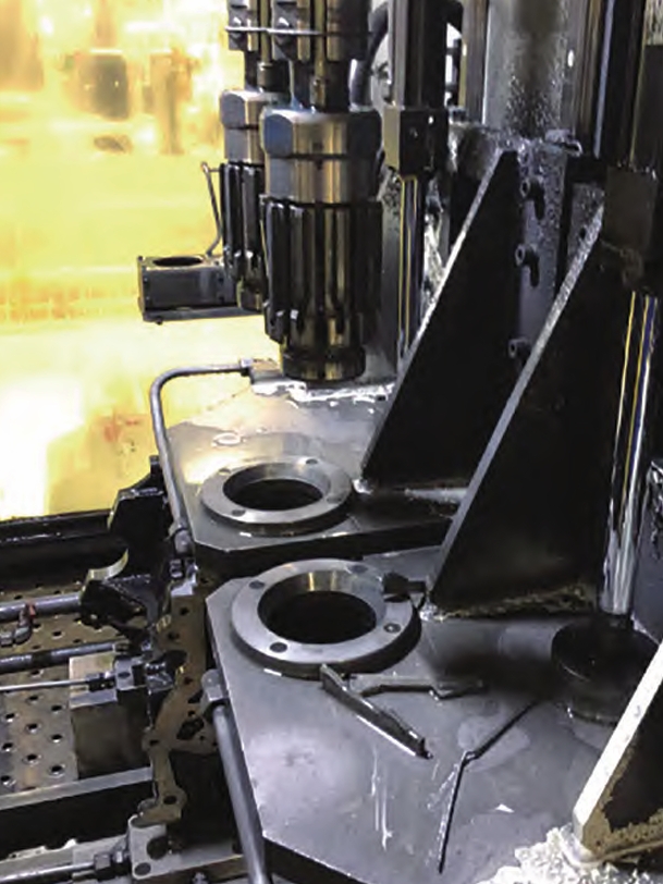
In another case, a foundry produced ductile iron flanged pipe fittings and grooved couplings. The castings showed sink marks on the flange surfaces. The sink was reduced by process adjustments and by controlling the silicon content, but after machining, small shrinkage porosity was still found in some locations. The residual porosity was scattered and not accessible to feeding from the riser. I recommended a pure lanthanum cored wire nodularization treatment. After the change, the shrinkage porosity was eliminated, and the sink tendency was also reduced. The late graphite expansion from the lanthanum treatment compensated for the last liquid contraction in the isolated flange sections. This was a clear demonstration that nodularizer selection can directly influence casting defects.
These case studies show a consistent pattern. When the casting geometry and molding method make riser and chill solutions impractical, the remaining practical variables are the silicon content, the carbon content, the carbon equivalent, the nodularizer type, and the inoculation practice. By controlling these variables, I can reduce the freezing range, delay early graphite precipitation, and promote late graphite expansion. The result is fewer casting defects, better pressure tightness, lower scrap, and higher process yield.
Process Design Rules I Use for Small Ductile Iron Castings
Based on my experience, I use the following rules when designing or troubleshooting small ductile iron castings. These rules are not a substitute for simulation or trial runs, but they provide a reliable starting point.
| Rule | Recommendation | Reason |
|---|---|---|
| Silicon content | Keep final Si at 2.5% to 2.8% for many small parts | Reduces freezing range and early graphite precipitation |
| Carbon content | Use the highest practical C, often 3.6% to 3.8% | Promotes graphite expansion and improves fluidity |
| Carbon equivalent | Target 4.3% to 4.5% | Maintains eutectic solidification without excessive Si |
| Nodularizer | Use pure lanthanum or lanthanum-rich treatment | Delays early graphite and promotes late graphite expansion |
| Inoculation | Avoid over-inoculation | Prevents uniform early graphite precipitation |
| Pouring temperature | Use the lowest temperature that fills the mold | Reduces liquid contraction and sand burn-on |
| Riser design | Use risers only when they can remain active | Small castings often freeze before riser feeding is effective |
| Chills | Use sparingly and locally | Excessive chilling can create hard spots and new defects |
I also use simple mass balance and volume balance checks. The liquid contraction before solidification can be estimated as:
$$ \Delta V_{\mathrm{liquid}} = \beta_{\mathrm{L}} \cdot V_{\mathrm{liquid}} \cdot \Delta T_{\mathrm{superheat}} $$
where \(\beta_{\mathrm{L}}\) is the volumetric contraction coefficient of the liquid, \(V_{\mathrm{liquid}}\) is the liquid volume, and \(\Delta T_{\mathrm{superheat}}\) is the superheat above the liquidus. The solidification contraction is approximately:
$$ \Delta V_{\mathrm{solidification}} = \beta_{\mathrm{S}} \cdot V_{\mathrm{solidifying}} $$
where \(\beta_{\mathrm{S}}\) is the solidification contraction coefficient. The solid contraction after freezing is:
$$ \Delta V_{\mathrm{solid}} = \beta_{\mathrm{alpha}} \cdot V_{\mathrm{solid}} \cdot \Delta T_{\mathrm{cooling}} $$
where \(\beta_{\mathrm{alpha}}\) is the coefficient of thermal contraction in the solid state. The graphite expansion is:
$$ \Delta V_{\mathrm{graphite}} = \frac{\rho_{\mathrm{iron}}}{\rho_{\mathrm{graphite}}} \cdot f_{\mathrm{graphite}} – f_{\mathrm{graphite}} $$
These equations are simplified, but they help me compare the relative importance of composition and process changes. In small ductile iron castings, the graphite expansion term is critically important because the casting modulus is small and the thermal gradient is low. If the graphite expansion is not timed correctly, it cannot compensate for the contraction. This is why I focus on silicon and nodularizer selection rather than only on riser size.
Defect Prevention Matrix
I often use a defect prevention matrix to organize my troubleshooting. The matrix below links the main causes of shrinkage and sink to the process variables I can control.
| Cause | Mechanism | Process Variable | Corrective Action |
|---|---|---|---|
| Wide freezing range | Mushy zone is broad, liquid pockets are isolated early | Silicon content, carbon equivalent | Reduce silicon, increase carbon within limits |
| Early graphite precipitation | Expansion occurs while gating is open and mold is compliant | Silicon, nodularizer, inoculation | Use pure lanthanum nodularizer, avoid over-inoculation |
| Insufficient late graphite expansion | Last liquid pockets cannot be fed | Carbon content, nodularizer | Increase carbon, use late-expansion nodularizer |
| Low temperature gradient | Hot spot and cold region are too close | Molding material, chill design | Use localized chilling only if it does not create new defects |
| Riser neck freezes early | Riser cannot feed the last liquid | Riser size, neck modulus | Improve modulus ratio or use self-feeding strategy |
| High pouring temperature | Increases liquid contraction and total shrinkage | Pouring temperature | Lower pouring temperature as much as filling allows |
This matrix has helped me move from reactive troubleshooting to proactive design. When I see a small ductile iron casting that is likely to show casting defects, I check the silicon content first. If it is above 2.9%, I consider reducing it. I then check the carbon content and carbon equivalent. If the carbon equivalent is acceptable but silicon is high, I increase carbon and decrease silicon while keeping the carbon equivalent in the desired range. Next, I review the nodularizer. If it is cerium-rich or if the inoculation is excessive, I consider a pure lanthanum treatment and a more controlled inoculation practice. Finally, I review the gating and riser design to ensure that the feeding path is not blocked prematurely.
Thermodynamic and Kinetic Considerations
From a thermodynamic perspective, silicon stabilizes the graphitic eutectic relative to the carbide eutectic. This is desirable because it prevents chill and promotes ferrite. However, from a kinetic perspective, silicon also increases the driving force for graphite growth. If the graphite grows too early, the expansion is wasted. If it grows too late, it cannot feed the last liquid. The ideal is a moderated driving force that is delayed by the nodularizer and by a lower silicon content.
The eutectic temperature can be expressed as:
$$ T_{\mathrm{eutectic}} = T_{\mathrm{Fe-C}} + m_{\mathrm{Si}} \cdot \mathrm{Si} + m_{\mathrm{Mn}} \cdot \mathrm{Mn} + \cdots $$
where \(T_{\mathrm{Fe-C}}\) is the reference eutectic temperature and \(m_{\mathrm{Si}}\) is the influence coefficient for silicon. Because silicon widens the difference between the stable and metastable eutectic temperatures, it increases the freezing range when both austenite and graphite are forming. In small castings with a low thermal gradient, this leads to a broad mushy zone and a high risk of casting defects.
The graphite growth rate can be approximated as:
$$ \frac{dR}{dt} = k_{\mathrm{g}} \cdot \left( a_{\mathrm{C}} – a_{\mathrm{C}}^{\mathrm{eq}} \right) $$
where \(R\) is the graphite nodule radius, \(k_{\mathrm{g}}\) is a kinetic coefficient, \(a_{\mathrm{C}}\) is the actual carbon activity, and \(a_{\mathrm{C}}^{\mathrm{eq}}\) is the equilibrium carbon activity. Silicon increases \(a_{\mathrm{C}}\), so \(\frac{dR}{dt}\) increases. A pure lanthanum nodularizer changes the local chemistry and interfacial conditions so that \(k_{\mathrm{g}}\) is effectively reduced in the early stage and increased in the late stage. This is a simplified way to explain the observed microstructure and feeding behavior.
Practical Guidelines for Foundry Trials
When I plan a trial to reduce casting defects in small ductile iron castings, I follow a step-by-step approach. First, I establish a baseline by measuring the silicon, carbon, and carbon equivalent of the current production heats. Second, I inspect the defects to confirm whether they are shrinkage or sink and to determine their location relative to the hot spots. Third, I simulate or estimate the solidification range and the modulus. Fourth, I design a trial with lower silicon, higher carbon, and a pure lanthanum nodularizer. Fifth, I evaluate the results by sectioning castings, checking pressure tightness, and comparing microstructure.
The trial matrix I use often looks like this:
| Trial | Final Si (%) | Final C (%) | Nodularizer | Expected Effect |
|---|---|---|---|---|
| A | 3.0 | 3.6 | Cerium-rich | Baseline, likely shrinkage |
| B | 2.8 | 3.7 | Cerium-rich | Moderate improvement |
| C | 2.7 | 3.7 | Pure lanthanum | Significant reduction in casting defects |
| D | 2.6 | 3.8 | Pure lanthanum | Further reduction, but check for chill |
I usually start with trial C because it balances the risk of chill with the benefit of late graphite expansion. If trial C succeeds, I may test trial D to see whether further silicon reduction improves feeding without causing carbides. If trial C shows chill, I adjust inoculation or slightly increase silicon while keeping the pure lanthanum nodularizer. The key is to change one variable at a time and to evaluate the results with sectioning and pressure testing, not only with visual inspection.
Economic and Quality Benefits
Reducing casting defects in small ductile iron castings has direct economic benefits. Lower shrinkage and sink mean lower scrap, less rework, fewer leak failures, and higher customer satisfaction. It also allows the foundry to reduce riser size or eliminate risers in some cases, which improves process yield. In addition, a lower silicon content can reduce alloy cost because ferrosilicon is expensive. A pure lanthanum nodularizer may have a different cost structure than a cerium-rich nodularizer, but the reduction in casting defects often justifies the change.
The quality benefits are also significant. Shrinkage porosity can reduce fatigue strength, pressure tightness, and machinability. Sink marks can cause dimensional problems and visual rejection. By controlling silicon and using a pure lanthanum nodularizer, I can improve the internal soundness and surface quality of small ductile iron castings. This is especially important for safety-related parts, hydraulic components, and automotive castings where casting defects are not acceptable.
Conclusion
In my experience, shrinkage and sink in small ductile iron castings are not solved by simply adding a larger riser or a stronger chill. These casting defects are rooted in the mushy solidification mode, the wide solidification temperature range, and the low temperature gradient that are typical of small, thin-wall parts. Silicon is a major factor because it widens the freezing range and increases early graphite precipitation. When silicon is too high, graphite expansion occurs too early, and the late expansion that could compensate for contraction is reduced. The result is a higher tendency for shrinkage and sink.
The most effective solution I have found is a combination of composition control and nodularizer selection. I keep final silicon in the range of 2.5% to 2.8% for many small castings, increase carbon to the highest practical level, and maintain a suitable carbon equivalent. I use a pure lanthanum magnesium-silicon nodularizer to delay early graphite precipitation and promote late graphite expansion. I avoid excessive inoculation because it can produce a uniform early graphite distribution that increases the risk of casting defects. I also use risers and chills only when they can remain effective, and I do not rely on them as the primary solution.
By applying these principles, I have solved shrinkage and sink problems in shell-molded small ductile iron parts and in flanged pipe fittings. The improvements were achieved without complex tooling changes and without reducing the required mechanical properties. The key was to understand the solidification behavior and to control the timing of graphite expansion. For foundries that produce small ductile iron castings, this approach offers a practical path to fewer casting defects, higher yield, and better quality.
I continue to refine these guidelines with additional trials and simulations. The optimal silicon range, carbon content, and nodularizer addition may vary with section thickness, molding material, and pouring practice. However, the underlying principles remain the same: narrow the freezing range, delay early graphite precipitation, promote late graphite expansion, and avoid process changes that create new casting defects. When these principles are followed, small ductile iron castings can be produced with significantly reduced shrinkage porosity and sink marks.