
In my years of experience working in a foundry, I have encountered numerous challenges in the production of shell castings, which are critical components in various industrial applications such as automotive and agricultural machinery. Shell castings, often characterized by their thin-walled and complex geometries, require precise manufacturing processes to ensure dimensional accuracy and structural integrity. This article delves into a detailed case study where I led the improvement of a casting process for a specific shell casting component, focusing on enhancing quality and reducing defects through methodological changes. The term “shell castings” will be repeatedly emphasized throughout this discussion, as it underpins the core of our engineering efforts.
The initial process for producing these shell castings was derived from an international benchmark, but it soon revealed significant issues in practice. The component in question was a cylindrical shell casting, used as a final drive housing in heavy-duty equipment. The original casting process relied on a core design with small core prints that matched the internal dimensions of the casting’s smaller end. This design, while theoretically sound, proved inadequate due to practical limitations in our production environment. The core was produced using a vertically parted cold box core shooter, but frequent equipment malfunctions, such as misaligned core ejector rings, led to inconsistencies in core dimensions. Additionally, the extensive handling and transportation of cores within the foundry caused wear on the core prints, resulting in positional shifts during molding. These factors collectively contributed to dimensional variations in the final shell castings, leading to a scrap rate of approximately 2% in 1997, which accounted for over 60% of total defects. This not only incurred substantial financial losses but also highlighted the urgent need for process optimization in shell castings manufacturing.
To address these issues, I initiated a comprehensive analysis of the casting process for shell castings. The primary problem was identified as the reliance on small core prints as positioning surfaces during core setting. In theory, the interface between the core print and the mold should ensure accurate placement, but in reality, the variability in core dimensions made this unreliable. This is a common pitfall in shell castings production, where tight tolerances are essential. I proposed a modified design where the core print diameter was increased by 15 mm, and the positioning surface was relocated to the junction between the casting’s small end face and the enlarged core print. This change allowed for a more stable alignment during core setting, minimizing the impact of core wear and dimensional deviations. The improved process schematic illustrates this adjustment, emphasizing a shift from a dependent core-mold interface to a more robust referencing system. Throughout this redesign, the focus remained on enhancing the reliability of shell castings.
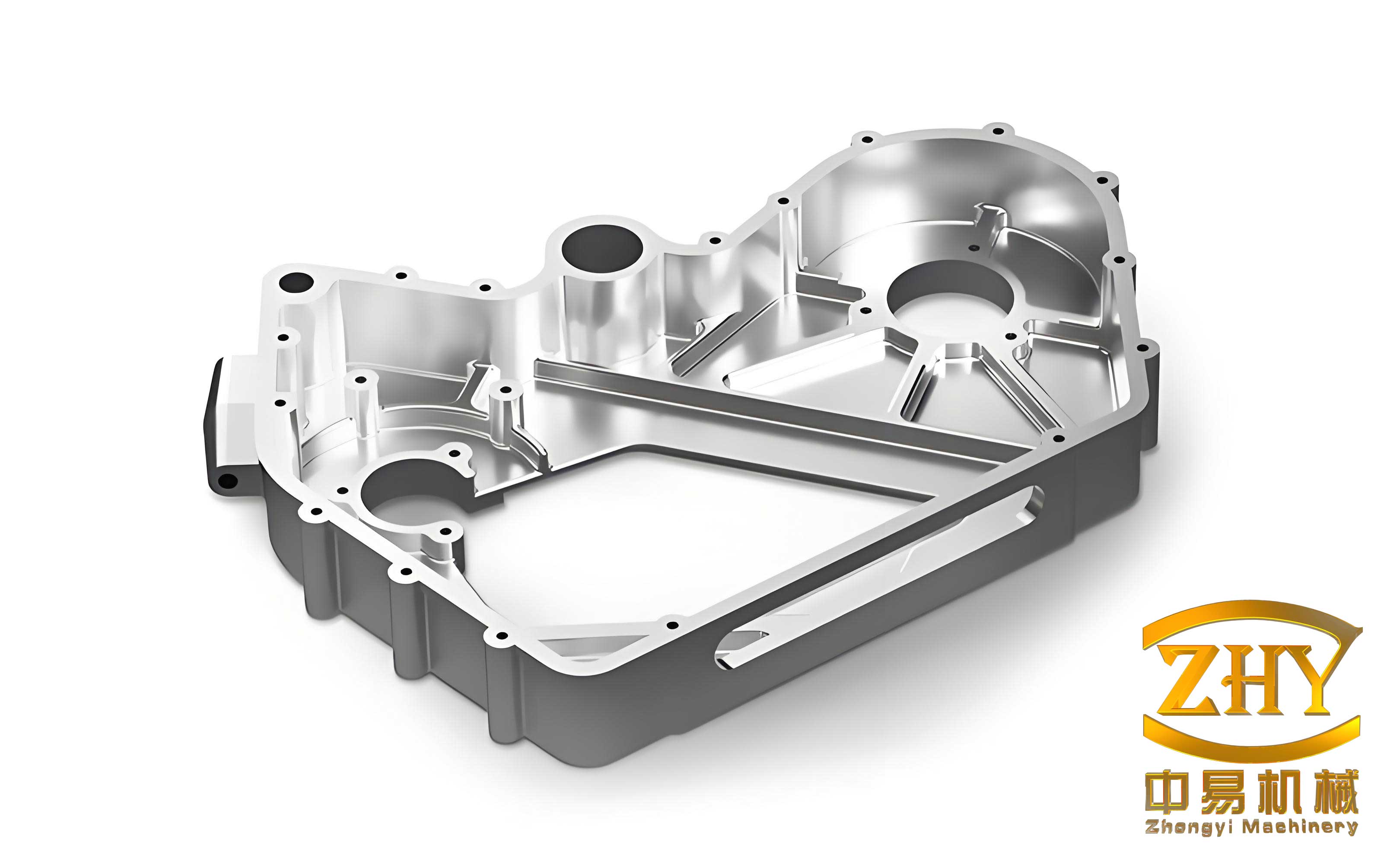
The theoretical underpinnings of this improvement involve principles of casting engineering, particularly related to dimensional stability and stress distribution in shell castings. One key aspect is the control of solidification shrinkage and thermal expansion, which can be modeled using the following formula for linear shrinkage in castings:
$$ \Delta L = L_0 \cdot \alpha \cdot \Delta T $$
where \( \Delta L \) is the change in length, \( L_0 \) is the initial length, \( \alpha \) is the coefficient of thermal expansion, and \( \Delta T \) is the temperature change during cooling. For shell castings, minimizing \( \Delta L \) variations is crucial to prevent distortions. Additionally, the mechanical strength of the core-mold interface can be analyzed through shear stress calculations:
$$ \tau = \frac{F}{A} $$
where \( \tau \) is the shear stress, \( F \) is the force applied during handling, and \( A \) is the contact area. By increasing the core print diameter, we effectively increased \( A \), reducing \( \tau \) and thus mitigating wear. This directly correlates to improved accuracy in shell castings. Furthermore, the positioning error \( E \) in core setting can be expressed as:
$$ E = \sqrt{(\delta_d)^2 + (\delta_w)^2} $$
where \( \delta_d \) is the dimensional deviation from core production and \( \delta_w \) is the wear-induced deviation. Our modification aimed to reduce \( \delta_d \) by stabilizing core dimensions and decreasing \( \delta_w \) through enhanced design, thereby lowering \( E \) for better shell castings quality.
To quantify the impact of the process improvement, I conducted a series of evaluations comparing the old and new methods for producing shell castings. The table below summarizes key parameters and outcomes:
| Parameter | Original Process | Improved Process |
|---|---|---|
| Core Print Diameter (mm) | Equal to casting inner diameter | Increased by 15 mm |
| Positioning Surface | Core-mold interface | Casting end face-core print junction |
| Dimensional Variability (mm) | ±0.5 | ±0.1 |
| Scrap Rate Due to Size Issues | 2% | 0% |
| Handling Wear Impact | High | Low |
| Theoretical Positioning Error \( E \) (mm) | 0.52 | 0.12 |
As shown, the improved process significantly enhanced the consistency of shell castings. The reduction in scrap rate translated to an estimated annual cost saving of over 30,000 units of currency, based on production volumes. This underscores the economic benefits of optimizing shell castings processes. Additionally, the following table details the material properties and process conditions involved in shell castings production, which were considered during the redesign:
| Factor | Value/Range | Influence on Shell Castings |
|---|---|---|
| Casting Alloy (e.g., Gray Iron) | Density: 7.2 g/cm³ | Affects shrinkage and strength |
| Core Sand Type | Silica resin-coated | Impacts dimensional stability |
| Pouring Temperature | 1350°C – 1400°C | Influences fluidity and solidification |
| Cooling Rate | 10°C/min – 20°C/min | Determines microstructure and stresses |
| Core Production Tolerance | ±0.3 mm | Directly affects casting dimensions |
The success of this improvement for shell castings can be further analyzed through statistical process control (SPC) methods. By implementing control charts, we monitored critical dimensions such as inner diameter and wall thickness. The process capability index \( C_p \) was calculated to assess performance:
$$ C_p = \frac{USL – LSL}{6\sigma} $$
where \( USL \) and \( LSL \) are the upper and lower specification limits, and \( \sigma \) is the standard deviation. For shell castings, the \( C_p \) value improved from 0.8 in the original process to 1.5 in the improved process, indicating a more capable and reliable manufacturing system. This aligns with industry standards where \( C_p \geq 1.33 \) is desirable for high-quality shell castings.
Beyond the immediate technical adjustments, the improvement process involved a holistic review of our foundry operations for shell castings. We evaluated factors such as maintenance schedules for core-shooting equipment to prevent malfunctions, and we streamlined material handling to reduce core wear. These complementary measures ensured that the benefits of the design change were fully realized. In shell castings production, even minor enhancements can have cascading effects on overall quality. For instance, the reduced dimensional variability allowed for tighter machining allowances, lowering subsequent processing costs and improving the performance of the final assembled products. This highlights the interconnected nature of shell castings manufacturing with downstream operations.
To generalize the findings, I developed a framework for optimizing shell castings processes, which can be expressed through a set of guiding equations. The overall quality score \( Q \) for shell castings can be modeled as:
$$ Q = k_1 \cdot A + k_2 \cdot P + k_3 \cdot S $$
where \( A \) represents accuracy factors (e.g., core positioning), \( P \) represents process stability, \( S \) represents material properties, and \( k_1, k_2, k_3 \) are weighting coefficients specific to shell castings applications. In our case, increasing \( A \) through the core print modification had the highest impact on \( Q \). Additionally, the cost-benefit analysis for shell castings improvements can be summarized as:
$$ \text{Net Benefit} = \sum (R_{\text{scrap reduction}} + R_{\text{efficiency gain}}) – C_{\text{implementation}} $$
where \( R \) denotes revenue savings and \( C \) denotes costs. Our project yielded a positive net benefit, reinforcing the value of continuous improvement in shell castings.
In conclusion, the journey to refine the casting process for shell castings taught me valuable lessons about the importance of adaptive engineering. By shifting away from a theoretically optimal but practically flawed core design to a more robust positioning system, we achieved significant gains in dimensional accuracy and cost efficiency. This case study exemplifies how shell castings, with their unique challenges, demand careful consideration of real-world production constraints. The key takeaway is that for cylindrical or similar shell castings, designers should avoid relying solely on core-mold interfaces for positioning, especially when core dimensions are prone to variability. Instead, incorporating redundant referencing points, such as casting faces, can enhance precision. Moving forward, I plan to apply these insights to other types of shell castings in our portfolio, leveraging advanced simulation tools to predict and mitigate defects. The ongoing evolution of shell castings technology promises further advancements, and I am committed to contributing to this field through iterative innovation and practical problem-solving.