
In the automotive industry, particularly for commercial vehicles, the V-shape thrust rod is an essential component within the balanced suspension system. It serves to transmit longitudinal and lateral loads, as well as corresponding moments, between the vehicle axle and frame, thereby ensuring stability and handling. Traditional manufacturing methods for these thrust rods often involve multiple processes such as forging, hot riveting, and friction welding. These approaches are not only complex and time-consuming but also introduce internal stresses, reduce precision, and increase overall production costs. To overcome these challenges, a novel strategy of replacing steel with nodular cast iron has been proposed and successfully implemented. This article details the comprehensive structural design, finite element analysis, manufacturing, and rigorous testing of a nodular cast iron V-shape thrust rod, emphasizing its benefits in weight reduction, cost efficiency, and enhanced performance. The adoption of nodular cast iron aligns with the automotive industry’s push toward lightweighting and sustainable manufacturing.
Traditional V-shape thrust rods typically comprise a steel tube connected to forged ball seats via joints created through hot riveting or friction welding. These joining techniques inherently introduce stress concentrations and potential weak points. Moreover, the multi-step production extends lead times and elevates costs. In contrast, nodular cast iron, also known as ductile iron, offers a compelling alternative due to its unique combination of high strength, good ductility, excellent castability, superior wear resistance, and inherent vibration damping capabilities. Crucially, nodular cast iron has a lower density (approximately 7.1-7.3 g/cm³) compared to forged steel (around 7.85 g/cm³), enabling significant weight savings. This property is vital for meeting stringent fuel efficiency and emission standards through vehicle lightweighting. Therefore, shifting to an integrated, one-piece casting design using nodular cast iron can streamline the production workflow, eliminate joint-related stresses, and enhance the component’s overall reliability and service life.
The core of this development lies in the innovative H-shaped integral structural design for the V-shape thrust rod using nodular cast iron. This design replaces the conventional assembly of separate tube and ball seats with a single, monolithic casting. The rod body features an H-shaped cross-section that smoothly transitions into the ball seats at both ends. This configuration not only improves structural integrity by providing superior bending and torsional stiffness compared to a circular tube but also is highly conducive to the casting process itself. The cross-sectional dimensions were carefully optimized, drawing inspiration from steel design standards while accounting for the specific properties of nodular cast iron. The primary goal was to meet or exceed the stiffness and fatigue performance requirements of the traditional steel component while actively reducing mass. Key geometric parameters defining the H-shaped cross-section are summarized in the table below.
| Parameter | Symbol | Value (mm) |
|---|---|---|
| Left Flange Height | H1 | 43.8 |
| Right Flange Height | H2 | 28.3 |
| Flange Top Thickness | m | 7.7 |
| Web Thickness | n | 7.0 |
| Overall Section Width | B | 51.1 |
The asymmetric flange heights (H1 and H2) were designed to optimize material distribution under complex loading, while the web and flange thicknesses ensure adequate strength. The H-shaped profile offers a higher moment of inertia than an equivalent circular cross-section, leading to better resistance against buckling and bending deformations. A detailed weight analysis confirmed that this nodular cast iron design achieves a mass reduction of approximately 9% compared to the traditional steel thrust rod. This saving stems from the elimination of solid forged ball ends and the overlapping joint regions required in the steel design, as well as the efficient use of material in the H-section. Furthermore, the one-piece casting process eliminates multiple welding or riveting steps, thereby reducing production time, energy consumption, and the risk of defects associated with those joining methods.
To rigorously evaluate the structural performance and ensure reliability, a comprehensive finite element analysis (FEA) was conducted. The full assembly model included the nodular cast iron thrust rod, alloy steel ball pins, end covers, rubber bushings (modeled as hyperelastic elements), and retaining rings. Pre-processing was performed using HyperMesh software. The mesh was carefully generated, employing higher-order tetrahedral elements (C3D10M) for the complex geometry of the nodular cast iron thrust rod to accurately capture stress gradients, and linear hexahedral elements (C3D8R) for other components. A mesh convergence study was performed to guarantee result accuracy, settling on a model with approximately 1.94 million elements. The material properties assigned in the simulation are critical and are listed in the following table.
| Material | Density (g/cm³) | Young’s Modulus, E (GPa) | Poisson’s Ratio, ν |
|---|---|---|---|
| Nodular Cast Iron (QT700-6) | 7.3 | 173 | 0.30 |
| Alloy Steel (for pins/covers) | 7.85 | 210 | 0.30 |
The rubber bushings were characterized using the Ogden hyperelastic material model, which accurately represents the non-linear stress-strain behavior of elastomers. The boundary conditions and loading scenarios were defined to replicate severe service conditions. Four distinct load cases were analyzed: Case 1 – Pure radial tensile load (150 kN); Case 2 – Pure radial compressive load (150 kN); Case 3 – Combined loading (simultaneous 150 kN axial and radial load); Case 4 – Pure torsional load (400 N·m). Constraints were applied to simulate the mounting conditions: the bolt holes on the two straight ball pins were fixed, and loads were applied at a coupling point defined at the center of the top ball pin. The linear elastic stress-strain relationship, governed by Hooke’s Law, is fundamental to this analysis:
$$ \sigma = E \epsilon $$
where $\sigma$ is the stress, $E$ is the material’s Young’s modulus, and $\epsilon$ is the strain. For nodular cast iron, the modulus of 173 GPa directly influences its deformation response under load.
The results of the static FEA for the nodular cast iron thrust rod revealed a favorable stress distribution. The maximum Von Mises stress under radial tension was 221.14 MPa, located at the retaining ring groove on the top ball seat—a region of geometric discontinuity. Under radial compression, the maximum stress decreased to 159.9 MPa. For the demanding combined loading case, the peak stress was 287.4 MPa. Under torsion, stresses were significantly lower, with a maximum of 38.79 MPa on the outer rib of the H-section. For comparison, an equivalent steel thrust rod model was analyzed under identical conditions. The steel design showed higher maximum stresses across all load cases: 288.9 MPa (tension), 219.7 MPa (compression), 403.6 MPa (combined), and 72.97 MPa (torsion). This comparative data is succinctly presented in the table below, clearly demonstrating the stress advantage of the nodular cast iron design.
| Loading Condition | Nodular Cast Iron Max Stress (MPa) | Steel Max Stress (MPa) |
|---|---|---|
| Radial Tension (150 kN) | 221.14 | 288.9 |
| Radial Compression (150 kN) | 159.9 | 219.7 |
| Combined Loading (150 kN) | 287.4 | 403.6 |
| Torsion (400 N·m) | 38.79 | 72.97 |
The safety factor ($SF$) for the nodular cast iron component can be calculated using the yield strength ($\sigma_y$) of the material and the maximum operational stress ($\sigma_{max}$) from FEA:
$$ SF = \frac{\sigma_y}{\sigma_{max}} $$
For the chosen as-cast QT700-6 grade nodular cast iron, the minimum specified yield strength is 420 MPa. Using the worst-case stress of 287.4 MPa from the combined loading simulation, the resultant safety factor is approximately 1.46, which is well within the acceptable range for automotive structural components. The selection of QT700-6 nodular cast iron is strategic. It is a pearlitic-grade iron that provides high strength and adequate toughness directly after casting, eliminating the need for costly and energy-intensive heat treatments like normalizing. This as-cast capability reduces manufacturing complexity, minimizes distortion risks, and shortens the production cycle. The target mechanical properties for QT700-6 are standardized as follows.
| Property | Minimum Value |
|---|---|
| Tensile Strength, Rm | 700 MPa |
| Yield Strength, Rp0.2 | 420 MPa |
| Elongation at Fracture, A | 6% |
| Brinell Hardness, HBW | 230 – 290 |
The manufacturing of the nodular cast iron V-shape thrust rod was carried out using a high-pressure green sand molding line, which ensures good dimensional accuracy and surface finish. The base iron was melted in a medium-frequency induction furnace. The critical spheroidization treatment, which transforms flake graphite into the vital spherical nodules, was achieved using the widely adopted sandwich method with a FeSiMg alloy. Post-inoculation was performed to refine the graphite structure. Precise control over the chemical composition is paramount for achieving the desired microstructure and properties. The target composition range for producing QT700-6 is detailed in the table below.
| Element | Content Range (%) |
|---|---|
| Carbon (C) | 3.7 – 3.9 |
| Silicon (Si) | 2.3 – 2.6 |
| Manganese (Mn) | 0.3 – 0.5 |
| Phosphorus (P) | < 0.05 |
| Sulfur (S) | 0.006 – 0.020 |
| Magnesium (Mg) | 0.040 – 0.050 |
| Copper (Cu) | 0.7 – 0.9 |
| Tin (Sn) | 0.01 – 0.02 |
| Chromium (Cr) | < 0.08 |
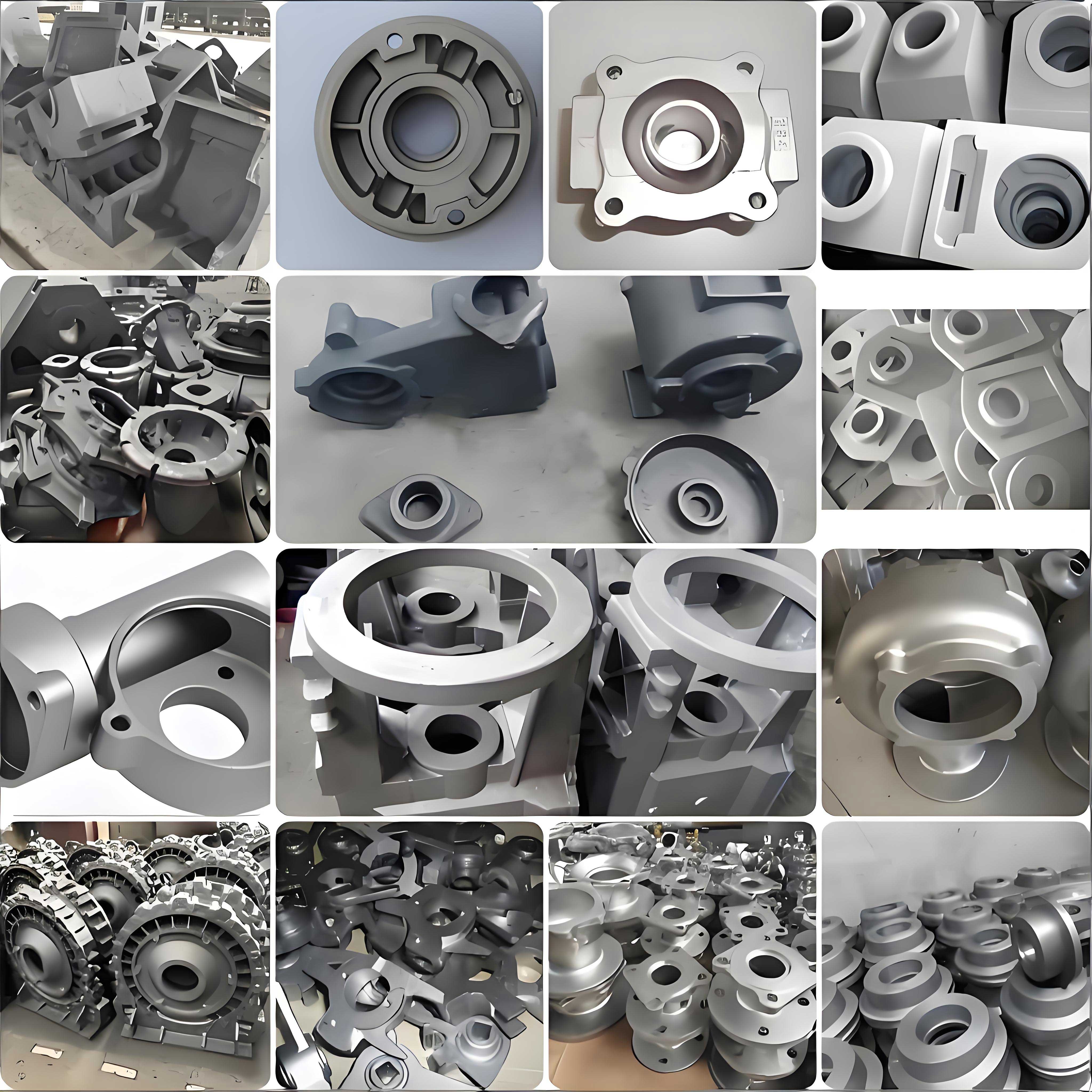
Copper and tin are added as pearlite stabilizers to ensure the required high strength in the as-cast condition. The pouring temperature was carefully controlled between 1380°C and 1400°C to ensure proper fluidity while minimizing gas pickup and shrinkage defects. After casting and cooling, the components underwent visual inspection and non-destructive testing via ultrasonic examination according to ASTM E446 standards. No significant internal defects such as shrinkage porosity or cavities were detected. The soundness of the casting process is visually apparent in the produced component.
Microstructural analysis is crucial for verifying the quality of nodular cast iron. Samples were taken from the thrust rod body, prepared metallographically, and examined under an optical microscope following GB/T 9441. The microstructure exhibited a matrix consisting predominantly of fine pearlite (approximately 80%) with a small amount of ferrite. The graphite was present in the form of well-dispersed, spherical nodules. Quantitative image analysis determined a nodule count of over 150 nodules per square millimeter, a spheroidization grade of 85%, and a graphite size rating of 6 (according to ASTM A247). This refined microstructure is the foundation of the material’s high strength and toughness. The spherical graphite nodules act as obstacles to crack propagation, significantly enhancing fracture toughness and fatigue resistance compared to materials with flake graphite. The relationship between microstructure and mechanical properties in nodular cast iron can be conceptually linked through composite mechanics models, where the effective properties depend on the matrix strength and the graphite morphology.
To confirm that the cast components met the QT700-6 specification, tensile and hardness tests were performed on specimens machined from the castings, specifically from the top ball seat region. The tests were conducted at room temperature using a servo-hydraulic universal testing machine and a Brinell hardness tester. The results from three representative specimens are compiled in the following table, demonstrating excellent consistency.
| Specimen ID | Tensile Strength (MPa) | Yield Strength (0.2% Offset) (MPa) | Elongation (%) | Brinell Hardness (HBW) |
|---|---|---|---|---|
| 1 | 765 | 440 | 6.9 | 253 |
| 2 | 780 | 443 | 7.2 | 249 |
| 3 | 748 | 434 | 6.7 | 259 |
| Average | 764 | 439 | 6.93 | 253.7 |
All average values comfortably exceed the minimum requirements for QT700-6 nodular cast iron, validating the success of the manufacturing process in producing high-integrity components with the desired high-strength, ductile characteristics.
A critical phase of the validation process involved static bench testing to correlate and verify the finite element analysis results. Electrical resistance strain gauges (uniaxial, 250 Ω) were bonded at nine strategic locations on the surface of the nodular cast iron thrust rod, primarily on the H-section web and flanges and the side of the top ball seat. The testing was performed using an MTS multi-axis servo-hydraulic test system. The thrust rod assembly was mounted to simulate its actual boundary conditions: the straight ball pins were bolted to a rigid fixture, and the load was applied to the top ball pin via a hydraulic actuator. The load was applied in a quasi-static manner, first in tension up to 150 kN and then in compression to -150 kN, with a loading rate of 5 kN/s. Strain data was recorded continuously using a high-precision data acquisition system. The experimentally measured strain ($\epsilon_{exp}$) was converted to stress ($\sigma_{exp}$) using the linear elastic formula with the experimentally validated Young’s modulus for the specific batch of nodular cast iron, which was 178 GPa.
$$ \sigma_{exp} = E_{exp} \cdot \epsilon_{exp} $$
The FEA model was probed at the exact same locations to extract the simulated stresses ($\sigma_{sim}$). The comparison between experimental and simulation results for both tensile and compressive loading is presented in the tables below. The relative error is calculated as:
$$ \text{Relative Error (\%)} = \frac{|\sigma_{exp} – \sigma_{sim}|}{\sigma_{exp}} \times 100 $$
| Strain Gauge Location | Experimental Stress (MPa) | FEA Simulated Stress (MPa) | Relative Error (%) |
|---|---|---|---|
| Point 1 | 134.8 | 115.3 | 14.5 |
| Point 2 | 83.3 | 75.2 | 9.7 |
| Point 3 | 89.2 | 81.8 | 8.3 |
| Point 4 | 16.0 | 14.4 | 10.0 |
| Point 5 | 81.2 | 75.4 | 7.1 |
| Point 6 | 96.8 | 85.7 | 11.5 |
| Point 7 | 80.3 | 75.2 | 6.4 |
| Point 8 | 10.9 | 12.3 | 13.8 |
| Point 9 | 92.0 | 83.3 | 9.5 |
| Strain Gauge Location | Experimental Stress (MPa) | FEA Simulated Stress (MPa) | Relative Error (%) |
|---|---|---|---|
| Point 1 | 101.1 | 78.9 | 21.9 |
| Point 2 | 74.9 | 79.9 | 6.8 |
| Point 3 | 62.7 | 71.6 | 14.2 |
| Point 4 | 27.4 | 24.1 | 12.0 |
| Point 5 | 84.6 | 76.8 | 9.2 |
| Point 6 | 95.4 | 85.7 | 10.2 |
| Point 7 | 79.0 | 85.8 | 8.6 |
| Point 8 | 8.3 | 9.8 | 18.1 |
| Point 9 | 71.6 | 80.5 | 12.4 |
For the tensile load case, all nine measurement points show a correlation error of less than 15%. For the compressive load case, seven out of the nine points exhibit errors within 15%, with two points showing slightly higher discrepancies. These variations can be attributed to factors such as minor deviations in exact gauge placement, slight material property anisotropies in the casting, and simplifications in the contact definitions within the FEA model. Overall, the strong correlation validates the accuracy and predictive capability of the finite element model for the nodular cast iron thrust rod design, providing confidence in its use for virtual prototyping and optimization.
The final and most demanding validation step involved fatigue durability testing. In service, the thrust rod is subjected to millions of load cycles, making fatigue performance a critical design criterion. Accelerated laboratory fatigue tests were conducted on complete thrust rod assemblies. The test setup applied fully reversed longitudinal cyclic loads (tension and compression) to the top ball pin while the straight pins were fixed. The load amplitude was set at ±150 kN, with a frequency of 1.5 Hz, simulating severe operating conditions. The test was run until a predefined limit of 200,000 cycles, which exceeds typical certification requirements for such components. The stiffness of the assembly (load vs. displacement) was monitored periodically throughout the test. The acceptance criteria required that the component show no visible cracks or failure and that the stiffness degradation remain below a threshold (typically 20%). The results for three tested assemblies are summarized below.
| Assembly Sample | Loading Condition | Stiffness Change After Test | Cycles Completed (×10³) | Post-Test Visual Inspection |
|---|---|---|---|---|
| A | ±150 kN, 1.5 Hz | +11.8% | 200 | No cracks, intact |
| B | ±150 kN, 1.5 Hz | +16.1% | 200 | No cracks, intact |
| C | ±150 kN, 1.5 Hz | +9.4% | 200 | No cracks, intact |
All three samples successfully endured 200,000 cycles without any sign of structural failure. The observed stiffness changes are positive (indicating slight stiffening, possibly due to seating of components or rubber bushing conditioning) and are well within the acceptable limit. This excellent fatigue performance is a direct result of the favorable stress distribution achieved by the H-shaped design and the inherent fatigue resistance of nodular cast iron. The fatigue life of metallic materials is often described by the Basquin equation in high-cycle fatigue regimes:
$$ \sigma_a = \sigma_f’ (2N_f)^b $$
where $\sigma_a$ is the stress amplitude, $N_f$ is the number of cycles to failure, and $\sigma_f’$ and $b$ are material constants. The high strength and spherical graphite morphology of QT700-6 nodular cast iron provide it with a high fatigue strength coefficient ($\sigma_f’$), contributing to its long service life under cyclic loads.
In conclusion, the development of the nodular cast iron V-shape thrust rod for commercial vehicles represents a significant technological advancement. The innovative H-shaped integral casting design, leveraging the superior properties of nodular cast iron, successfully addresses the limitations of traditional steel thrust rods. Key achievements include a 9% reduction in component weight, contributing directly to vehicle lightweighting goals; the elimination of internal stresses associated with welding or riveting; and a simplified, cost-effective manufacturing process. Extensive finite element analysis confirmed that the nodular cast iron design exhibits lower maximum stresses under equivalent loading conditions compared to its steel counterpart. The material selection of as-cast QT700-6 nodular cast iron was validated through rigorous metallurgical and mechanical testing, proving its capability to meet high strength and ductility requirements without post-casting heat treatment. Static and fatigue bench tests provided strong experimental correlation with simulation models and demonstrated exceptional durability, with components surviving 200,000 severe load cycles without failure. This project underscores the immense potential of nodular cast iron as a high-performance, economical, and sustainable material solution for structural automotive components. It paves the way for further exploration of integrated cast designs using nodular cast iron in other chassis and powertrain applications, driving forward the goals of efficiency, reliability, and cost-effectiveness in commercial vehicle engineering.