
In my extensive experience with lost foam casting, I have found it to be a highly advantageous process for producing complex components, particularly those made from nodular cast iron. The benefits of excellent surface finish, dimensional accuracy, and high yield are well-documented. This process is ideally suited for manufacturing parts like reducer housings, which demand high strength, toughness, wear resistance, and seismic performance. The material of choice is often QT450-10 nodular cast iron. However, during initial trial productions of such a reducer housing—weighing 112 kg with wall thicknesses ranging from 14 mm to 54 mm and concentrated geometric hot spots—I encountered significant casting defects: surface wrinkling and shrinkage porosity. This article details my investigation into these defects, the root cause analysis, and the innovative solutions I developed and validated.
The reducer housing is a critical component, and its performance hinges on the integrity of the nodular cast iron structure. The original casting process, as implemented in my foundry, utilized a top-gating system. The key process parameters were: a pouring temperature of 1,370–1,440 °C, a furnace tap temperature of 1,580–1,600 °C, a casting negative pressure of -0.04 to -0.06 MPa, and a negative pressure holding time of 900 seconds. A 4 mm machining allowance was designed on the end face. The chemical composition of the QT450-10 nodular cast iron used is presented in the table below.
| Element | Content (wt.%) |
|---|---|
| C | 3.5 – 4.0 |
| Si | 2.0 – 3.0 |
| Mn | ≤ 0.45 |
| P | ≤ 0.05 |
| S | ≤ 0.025 |
| Mg | 0.02 – 0.06 |
| RE | 0.015 – 0.04 |
While Y-block test samples met the QT450-10 mechanical property requirements and achieved a nodularity grade of 2-3, the actual castings from the lost foam process exhibited unacceptable defects. Surface wrinkling appeared on the upper end faces, and shrinkage cavities were consistently found in the thick sections surrounding bolt holes, which are geometric hot spots. These defects threatened the structural integrity and machinability of the nodular cast iron housing.
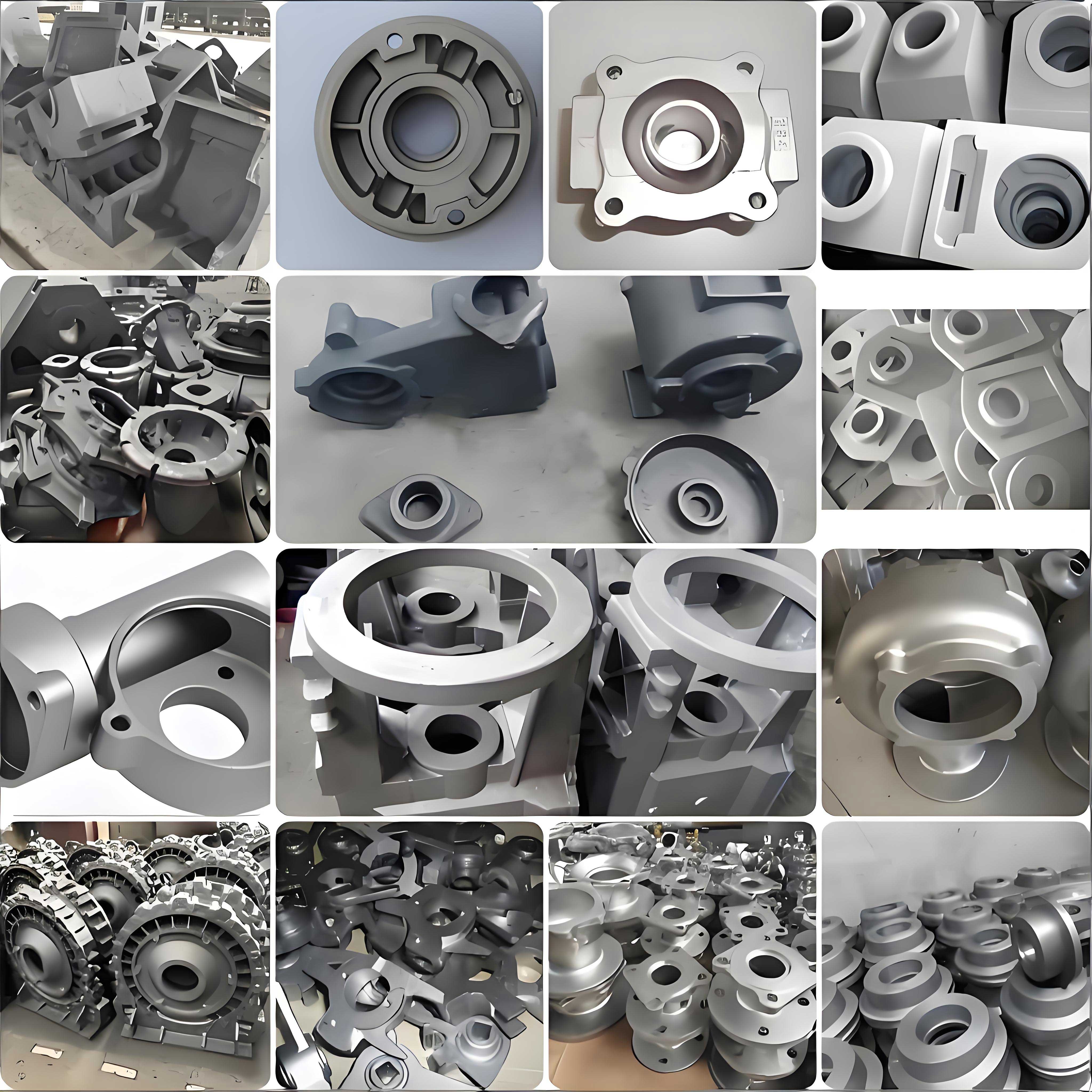
To understand the wrinkling defect, one must delve into the fundamentals of lost foam casting of nodular cast iron. The foam pattern, typically made from a co-polymer material to balance gas generation and solid carbon residue, decomposes upon contact with the molten metal. This decomposition produces gaseous, liquid, and solid pyrolysis products. The transport and interaction of these products with the advancing metal front are complex. Wrinkling, a form of carbon defect, manifests as a rough, orange-peel-like surface on the final casting. It predominantly occurs in areas where metal flow is last to arrive or in “cold zones” where heat transfer is inefficient, such as the top surfaces, vertical side walls, or blind pockets of the mold cavity.
In the original top-gating design, the molten nodular cast iron entered from the top of the pattern. However, due to the part geometry—a thick upper section (35-50mm) abruptly transitioning to a thin lower section (13mm)—the flow did not follow a simple top-down progression. Instead, the metal stream penetrated the thick top section, using the cavity itself as a runner, and then fanned out downwards through the thin walls. This created a highly turbulent, mid-bottom filling sequence. The turbulence disrupted the orderly displacement of pattern decomposition products. Furthermore, the thick upper regions and side pockets became effective “cold zones” where cooler metal and insufficiently vaporized pattern residues accumulated, leading to the formation of surface wrinkles. The filling behavior can be partially described by fluid flow principles. The Reynolds number (Re) for flow in a channel indicates turbulence:
$$Re = \frac{\rho v D_h}{\mu}$$
where $\rho$ is the density of molten nodular cast iron, $v$ is the flow velocity, $D_h$ is the hydraulic diameter of the flow channel, and $\mu$ is the dynamic viscosity. The original gating likely resulted in a high $Re$, causing turbulent flow that entrapped pyrolysis products at the metal front.
The shrinkage cavities in the nodular cast iron housing had a different origin. Given that the chemical composition, nodularization, and inoculation were within specification, and other casting parameters like temperature and negative pressure were controlled, the primary cause was identified as inadequate feeding during solidification. Nodular cast iron, despite its good feeding characteristics due to graphite expansion, is still susceptible to shrinkage in isolated hot spots. The volumetric contraction during liquid cooling and solidification must be compensated by liquid metal feed. If a thermal hot spot—a region with a high modulus (volume-to-surface-area ratio)—solidifies last without access to feed metal, a shrinkage pore forms. The local solidification time $t_f$ is related to the modulus $M$ by Chvorinov’s rule:
$$t_f = B \cdot M^n$$
where $B$ and $n$ are constants dependent on the mold material and metal properties. For the thick bolt boss areas on the housing, the modulus $M$ was high, leading to a long local solidification time and creating a demand for feed metal that could not be met.
My approach to solving these defects was twofold, addressing each problem with a targeted modification to the casting process.
Solution for Wrinkling: Gating System Optimization
I completely redesigned the gating system from a top-gate to a fully bottom-gate, closed system. The objective was to achieve calm, laminar filling from the bottom upwards, allowing pyrolysis gases to escape upwards through the coating and sand without being trapped, and ensuring that the cooler, leading edge of the metal with concentrated residues would be pushed to the top machining allowance where it would be removed. I performed theoretical calculations to size the new gating system. First, the pouring time $t$ was estimated based on empirical formulas for cast iron:
$$t = S \sqrt{G_L} \approx 24 \text{ seconds}$$
where $S$ is a coefficient (typically 2.0 for medium-sized castings) and $G_L$ is the poured weight in kg. For a bottom-gated system, the effective metallostatic pressure head $H_p$ is critical:
$$H_p = H_0 – \frac{C}{2} = 34 \text{ cm}$$
where $H_0$ is the total height of the sprue and $C$ is the height of the casting in the mold. The minimum required choke area (at the ingates) $A_g$ was calculated using the Bernoulli-based equation:
$$A_g = \frac{G}{0.31 t \mu \sqrt{H_p}}$$
where $\mu$ is the flow coefficient (taken as 0.8 for a bottom-gated system). This yielded $A_g \approx 3.46 \text{ cm}^2$. Considering the inherent higher resistance in lost foam casting due to foam decomposition, I applied a safety factor. I also consulted empirical charts for nodular cast iron gating, which suggested a range of 3.5 to 12 cm². I designed a central sprue with four ingates, each with dimensions of 70 mm x 40 mm, giving a total ingate area of 11.2 to 12.8 cm². This ensured a sufficiently large area to reduce metal velocity and promote laminar flow. The sprue height was set to 480 mm to maintain adequate pressure head. This new design facilitated sequential, bottom-up filling, eliminating the turbulent “cold zones” responsible for wrinkling.
Solution for Shrinkage: Innovative Heat Dissipation Pad Process
Traditional methods to eliminate shrinkage in nodular cast iron, such as using large feeders (risers) or external chills, were not ideal for this lost foam application. Feeders would drastically reduce the process yield and complicate pattern assembly. External chills are difficult to position reliably in lost foam molds and can cause dimensional instability or chilling defects in ductile iron. I conceived and developed a novel “Heat Dissipation Pad” process. The core principle is to modify the effective geometry of the casting in the mold to increase the surface area for heat transfer at the hot spot, thereby reducing its modulus and creating a directional solidification effect.
Specifically, I attached low-density foam pads (the “dissipation pads”) onto the EPS pattern at the identified geometric hot spots—the thick bolt boss areas. These pads, with dimensions of 50 mm x 30 mm x 7 mm, become integral parts of the pattern assembly. After coating, drying, and sand filling, the mold contains these pad cavities adjacent to the casting. During pouring and solidification, the continuous application of negative pressure (-0.04 to -0.06 MPa) causes cold air to be drawn through the permeable sand. This air flows around the casting and, most importantly, through the intricate channels formed by the sand surrounding the dissipation pads. The pads dramatically increase the effective surface area $A_s$ for heat exchange at the hot spot. The local modulus $M_{local}$ is defined as:
$$M_{local} = \frac{V}{A_s}$$
where $V$ is the volume of the metal in the hot spot region. By attaching the pad, $A_s$ increases significantly, thus decreasing $M_{local}$. A lower modulus translates to a shorter local solidification time, moving the solidification sequence forward and allowing the hotter, still-liquid metal from the surrounding thinner sections to feed the area. The process acts as an effective “air-cooled chill.” The heat removal rate $\dot{Q}$ can be approximated by convective heat transfer:
$$\dot{Q} = h A_s (T_s – T_\infty)$$
where $h$ is the convective heat transfer coefficient enhanced by forced convection from the negative pressure draft, $T_s$ is the surface temperature of the nodular cast iron, and $T_\infty$ is the temperature of the incoming sand/air. The table below summarizes the key changes in the process before and after optimization.
| Process Aspect | Original Process | Optimized Process |
|---|---|---|
| Gating System | Top-gating, turbulent fill | Bottom-gating, laminar fill |
| Ingate Total Area | Not explicitly stated, but likely smaller | 11.2 – 12.8 cm² (4 ingates) |
| Filling Sequence | Mid-bottom, turbulent | Bottom-up, sequential |
| Shrinkage Mitigation | None specifically for hot spots | Heat Dissipation Pads attached to hot spots |
| Modification Complexity | Simple pattern | Pattern with added foam pads (simple attachment) |
| Process Yield | Potentially lower due to defects | High, no major yield loss from pads or oversized gating |
To validate these solutions, I conducted production trials. For the gating modification, a batch of 2,000 reducer housings was produced using the new bottom-gated system. The results were definitive: the surface wrinkling defect on the end faces was completely eliminated. The castings exhibited a smooth, clean surface suitable for machining. The successful application of bottom-gating for nodular cast iron in lost foam casting underscores the importance of controlled fluid dynamics to manage foam decomposition products.
The heat dissipation pad process was tested specifically on the problematic bolt boss regions. After attaching twelve 50x30x7 mm foam pads to the pattern at these hot spots, castings were produced and subsequently machined. Post-machining inspection of the bolt holes confirmed the complete absence of subsurface shrinkage cavities. This trial was followed by a sustained production run of over 2,000 pieces using this methodology, with no recurrence of the shrinkage defect. The pads are consumed during casting, leaving no residue, and the subsequent cleaning operation is straightforward, involving only the removal of the burned-out coating from the pad cavities. This method proved to be a simple, cost-effective, and high-yield alternative to traditional feeding methods for nodular cast iron in the lost foam process.
The table below provides a comparative analysis of the defect mechanisms and the corresponding solutions, emphasizing the scientific principles involved.
| Defect Type | Root Cause (Scientific Principle) | Solution Implemented | Governing Principle of Solution |
|---|---|---|---|
| Surface Wrinkling | Turbulent flow entraining foam pyrolysis products; formation of cold zones (Fluid Dynamics & Heat Transfer) | Bottom-gating system redesign | Promotion of laminar flow (Low Reynolds Number regime); sequential displacement of decomposition gases. |
| Shrinkage Cavity | High local modulus leading to delayed solidification and inadequate feeding (Solidification Theory) | Heat Dissipation Pad process | Artificial increase of surface area to reduce local modulus $M$; enhanced convective cooling creating directional solidification. |
In conclusion, my investigation into the defects plaguing the lost foam production of a nodular cast iron reducer housing led to two significant process innovations. First, the systematic redesign of the gating system from top to bottom pouring resolved the surface wrinkling issue by fundamentally altering the fluid flow characteristics during mold filling. This change ensured that the production of high-quality nodular cast iron surfaces became consistent and reliable. Second, and perhaps more innovatively, I developed the Heat Dissipation Pad process to address isolated shrinkage in geometric hot spots. This method elegantly circumvents the drawbacks of conventional feeders and chills in lost foam casting. By leveraging the inherent negative pressure of the process to enhance convective cooling from strategically attached foam pads, I successfully reduced the local modulus of hot spots, thereby eliminating shrinkage porosity in the nodular cast iron. Both solutions are characterized by their simplicity, high process yield, and effectiveness. They represent valuable strategies for enhancing the quality and reliability of lost foam cast components, particularly for demanding materials like nodular cast iron. The successful production of thousands of defect-free reducer housings stands as a testament to the robustness of these optimized processes. Future work could involve further parametric optimization of the pad geometry and placement using solidification simulation software to maximize efficiency for even more complex nodular cast iron castings.