
In our foundry operations, we faced a persistent issue with water-ring vacuum pump housings fabricated from welded steel plates. Over time, these components experienced leakage due to prolonged erosion from water and sand particles, leading to reduced vacuum system pressure and compromised casting production efficiency and quality. To address this, we decided to adopt nodular cast iron for manufacturing the vacuum pump housing castings, aiming to enhance durability and service life. This article details our comprehensive approach using the lost foam casting process, focusing on design, simulation, and production control to achieve a high-integrity, leak-free component.
The transition to nodular cast iron was driven by its superior mechanical properties, including high strength, ductility, and wear resistance, which are critical for applications involving fluid dynamics and abrasive environments. The housing’s large dimensions—maximum outer diameter of 864 mm, height of 637 mm, and a wall thickness of 35 mm in the cylinder section—presented significant challenges in casting integrity. The single casting weight is 425 kg, and the material specification requires QT600-3 grade nodular cast iron with strict non-leakage criteria. Our strategy involved a meticulous casting method design, supported by 3D simulation, to ensure defect-free production.
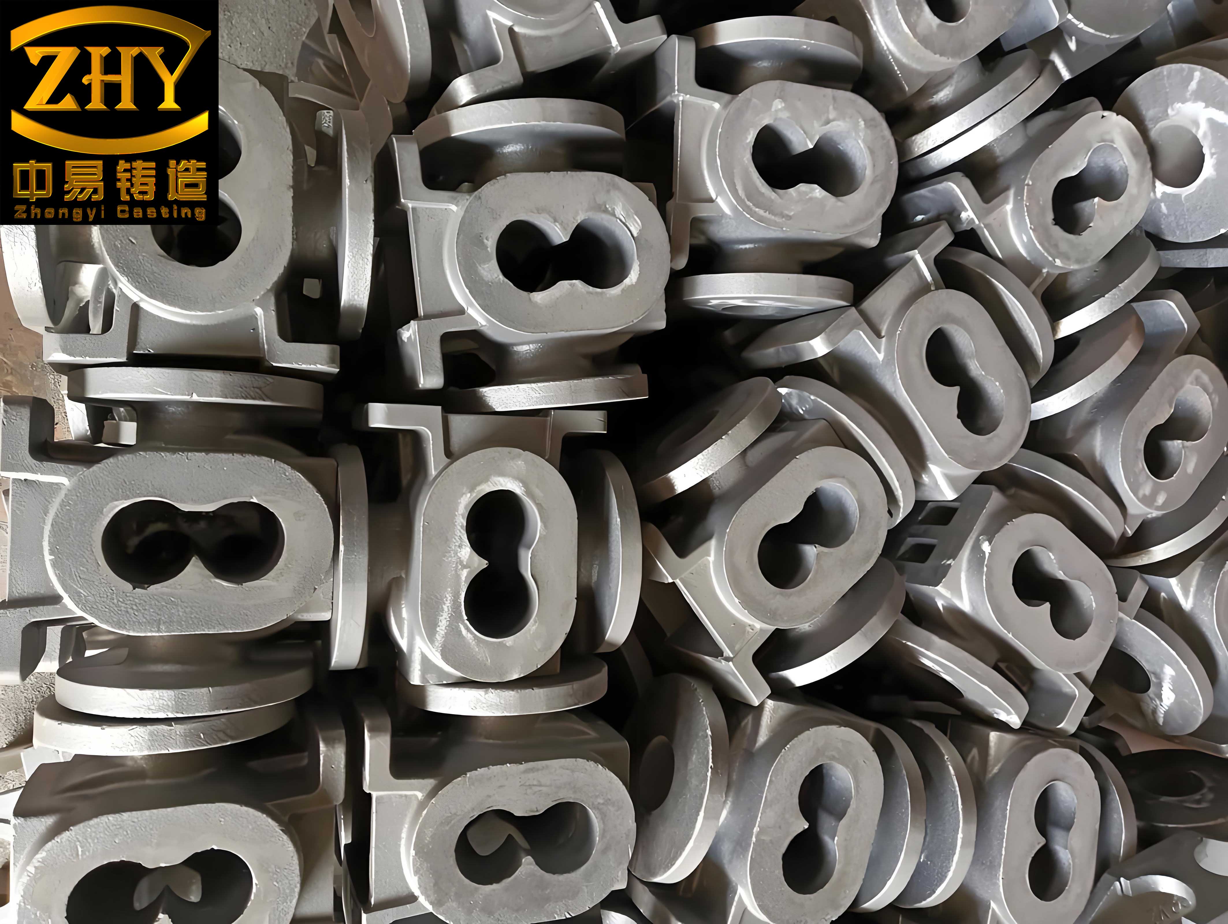
The casting process was designed for a single mold per flask, using a flask size of 1200 mm × 1000 mm × 1300 mm. The total weight per flask, including the casting and gating system, was 560 kg. We employed a 700 kg ladle for iron tapping and utilized a cored wire injection method for nodularization, which is efficient for nodular cast iron production. The pouring temperature was set between 1430°C and 1450°C, with a vacuum negative pressure maintained at -0.05 to -0.06 MPa during pouring. To prevent distortion, the pressure was held for one hour after pouring. The gating system adopted a top-pouring, semi-open design with a gating ratio of ΣFsprue : ΣFrunner : ΣFingate = 1 : 1.4 : 1.2. Key dimensions included a sprue diameter of 50 mm, runner cross-section of 75 mm × 75 mm, and ingate cross-section of 40 mm × 140 mm. Six risers, each 120 mm × 120 mm × 140 mm, were evenly placed on the top of the casting to facilitate feeding and eliminate shrinkage defects.
To validate the design, we conducted numerical simulations using MAGMA software, analyzing both mold filling and solidification processes. The simulation results confirmed that the top-pouring approach ensured orderly filling: molten iron entered the cavity through the gating system, descended to the bottom, and then rose uniformly, with cooler iron at the lower sections being progressively fed by hotter metal from above. This promoted sequential solidification, with the risers solidifying last to provide effective feeding. The simulations indicated no significant isolated liquid zones, suggesting that any minor shrinkage could be compensated by graphite expansion inherent to nodular cast iron. The governing equations for solidification time and feeding requirements can be expressed using Chvorinov’s rule and thermal modulus concepts. For instance, the solidification time \( t_s \) for a casting section can be approximated as:
$$ t_s = k \left( \frac{V}{A} \right)^2 $$
where \( V \) is the volume, \( A \) is the surface area, and \( k \) is a constant dependent on mold material and metal properties. In our design, the modulus method was applied to ensure risers had a higher modulus than the casting sections they fed, calculated as:
$$ M = \frac{V}{A} $$
For the cylinder section with a wall thickness of 35 mm, the modulus was approximately 17.5 mm, while the risers, with dimensions of 120 mm × 120 mm × 140 mm, had a modulus of about 30 mm, ensuring adequate feeding capacity. The following table summarizes key casting parameters:
| Parameter | Value |
|---|---|
| Casting Weight | 425 kg |
| Flask Dimensions | 1200 mm × 1000 mm × 1300 mm |
| Pouring Temperature | 1430–1450°C |
| Vacuum Pressure | -0.05 to -0.06 MPa |
| Gating Ratio (Sprue:Runner:Ingate) | 1 : 1.4 : 1.2 |
| Riser Dimensions | 120 mm × 120 mm × 140 mm |
| Solidification Time (Estimated) | ~90 minutes |
The lost foam pattern process required careful pattern fabrication due to the large size. Using CAD software, the housing was decomposed into multiple segments: 12 pieces for the cylinder and 8 pieces for the end flanges, with fillet radii of R10 mm joined using fine foam strips. This segmentation allowed for precise CNC cutting on an automated platform. The assembly involved manual bonding on a glass plate aligned to the center, with fiber rods used for temporary fixation. Gaps were sealed with adhesive and tape to prevent coating infiltration during dipping. To counteract deformation, wooden strips (15 mm × 15 mm cross-section) were bonded to the pattern’s upper and lower sections. The gating system and risers were attached using fiber rods for reinforcement. The pattern assembly ensured dimensional accuracy, critical for the final nodular cast iron casting.
Coating application was performed through dipping, with the pattern slowly rotated to achieve uniform coverage. A secondary manual pouring was used for hard-to-reach areas. The coating was applied in four layers to a Baumé density of 69–71 °Bé, enhancing mold strength and preventing metal penetration. After dipping, the patterns were dried in a dedicated oven to remove moisture. The molding involved placing the coated pattern in a flask, followed by vibration-compacted dry sand for 90 seconds to ensure proper filling and support. This process is vital for maintaining cavity integrity during pouring of nodular cast iron.
The melting and treatment of nodular cast iron were crucial to meet the QT600-3 specifications. We used a charge composition targeting the following chemical ranges, optimized for high strength and nodularity:
| Element | Target Composition (wt%) |
|---|---|
| Carbon (C) | 3.6–3.8 |
| Silicon (Si) – Post-nodularization | 2.3–2.5 |
| Manganese (Mn) | 0.4–0.6 |
| Sulfur (S) | ≤0.02 |
| Phosphorus (P) | ≤0.05 |
| Residual Magnesium (Mg) | 0.04–0.06 |
| Tin (Sn) | 0.05–0.07 |
Nodularization was achieved via a tundish cover ladle process with double cored wires, injecting FeSiMg25Re3 alloy at 0.7% addition rate. This method minimizes oxidation and ensures consistent magnesium recovery, essential for forming spheroidal graphite in nodular cast iron. In-mold inoculation involved 0.3% preconditioner and 0.2% 75FeSi composite inoculant to refine graphite structure. The cored wire injection parameters, such as speed and length, were controlled by PLC, with the reaction described by kinetic equations for magnesium assimilation:
$$ \text{Mg recovery} = \frac{\text{Mg absorbed}}{\text{Mg added}} \times 100\% $$
Typically, we achieved recovery rates above 85%, contributing to a nodularity grade of 2 or better. After treatment, slag was rapidly removed, and the ladle was transported for pouring. To mitigate shrinkage, temperature control was strict: if the iron exceeded 1450°C, cold iron chunks were added to cool it, and the mold was topped up after initial pouring to ensure riser feeding.
Production trials yielded castings that underwent rigorous inspection. Attached test bars were evaluated for microstructure and mechanical properties, as summarized below:
| Property | Result |
|---|---|
| Nodularity Grade | 2 |
| Graphite Size Grade | 7 |
| Pearlite Volume Fraction | 65% |
| Cementite Volume Fraction | ≤1.0% |
| Phosphide Eutectic Volume Fraction | ≤0.5% |
| Tensile Strength | 641 MPa |
| Elongation | 3.5% |
The microstructure exhibited well-dispersed spheroidal graphite in a pearlitic matrix, confirming the suitability of nodular cast iron for this application. After shakeout, risers were removed via cutting, revealing no shrinkage cavities or porosity. Dimensional checks aligned with design specifications, and machining trials showed no defects like sand inclusions or holes, meeting the vacuum pump’s operational requirements.
Further analysis of the process efficiency can be modeled using quality yield equations. The casting yield \( Y \) is defined as:
$$ Y = \frac{W_c}{W_t} \times 100\% $$
where \( W_c \) is the casting weight (425 kg) and \( W_t \) is the total poured weight (560 kg), giving a yield of approximately 76%. This is acceptable for complex nodular cast iron castings. Additionally, the feeding efficiency of risers can be expressed as:
$$ \text{Feeding Efficiency} = \frac{V_f}{V_c} $$
with \( V_f \) as the fed volume from risers and \( V_c \) as the casting volume. Our design ensured this ratio was above 1.2, preventing macro-shrinkage.
In conclusion, our implementation of lost foam casting for thick-section nodular cast iron vacuum pump housings proved highly effective. The pattern fabrication via CNC cutting and manual assembly enabled precise dimensions, suitable for small-batch production. The cored wire nodularization process, particularly the double-wire method under a tundish cover, guaranteed consistent magnesium treatment and high-quality nodular cast iron. The top-pouring gating system coupled with riser feeding promoted orderly filling and directional solidification, resulting in dense, leak-free castings. This approach not only resolved the leakage issues of welded steel housings but also optimized production for durability and performance. Future work could explore automated pattern assembly or advanced simulation techniques to further refine the process for other large nodular cast iron components.