
In my extensive experience within the foundry industry, I have encountered numerous challenges related to casting defects, but few are as persistent and economically damaging as shrinkage porosity in nodular cast iron components. Nodular cast iron, renowned for its high strength and ductility due to the spherical graphite morphology in its microstructure, is a preferred material for critical parts subjected to complex stresses. However, its solidification characteristics—notably a significant expansion during the eutectic reaction followed by contraction—often lead to shrinkage defects like porosity and cavities, especially in sand casting processes. These defects frequently remain undetected until machining or pressure testing, resulting in costly rework, quality claims, and delivery delays that tarnish a company’s reputation. This article, drawn from my firsthand investigations, delves into a detailed case study of a nodular cast iron shell casting, analyzing the root causes of shrinkage porosity and presenting effective countermeasures that enabled successful mass production.
The fundamental issue stems from the unique solidification behavior of nodular cast iron. Unlike gray iron, the graphite spheroids in nodular cast iron form during eutectic solidification, generating substantial internal expansion pressure. In rigid sand molds, this expansion can compensate for the liquid and solidification shrinkage, a phenomenon termed “self-feeding.” However, if the process conditions are not optimized, the compensation is incomplete, leading to internal voids or shrinkage porosity. The propensity for shrinkage in nodular cast iron is often quantified using the concept of the shrinkage tendency, which can be related to the carbon equivalent (CE) and cooling rates. A simplified theoretical model for the volume change during solidification can be expressed as:
$$ \Delta V_{total} = \Delta V_{liquid} + \Delta V_{solidification} + \Delta V_{graphite\,expansion} $$
Where $\Delta V_{liquid}$ is the contraction of the liquid as it cools to the liquidus temperature, $\Delta V_{solidification}$ is the contraction during the phase change from liquid to austenite-graphite eutectic, and $\Delta V_{graphite\,expansion}$ is the expansion due to graphite precipitation. For shrinkage to be avoided, the expansion must outweigh the contraction: $\Delta V_{graphite\,expansion} \geq |\Delta V_{liquid} + \Delta V_{solidification}|$. The carbon equivalent, a key parameter for nodular cast iron, significantly influences this balance. It is calculated as:
$$ CE = \%C + \frac{\%Si + \%P}{3} $$
For typical nodular cast iron like QT500-7, the target CE range is often near the eutectic point (approximately 4.3-4.7%). A higher CE promotes better graphiteization, enhancing the expansion component and improving fluidity. The interplay of these factors dictates the final soundness of the casting.
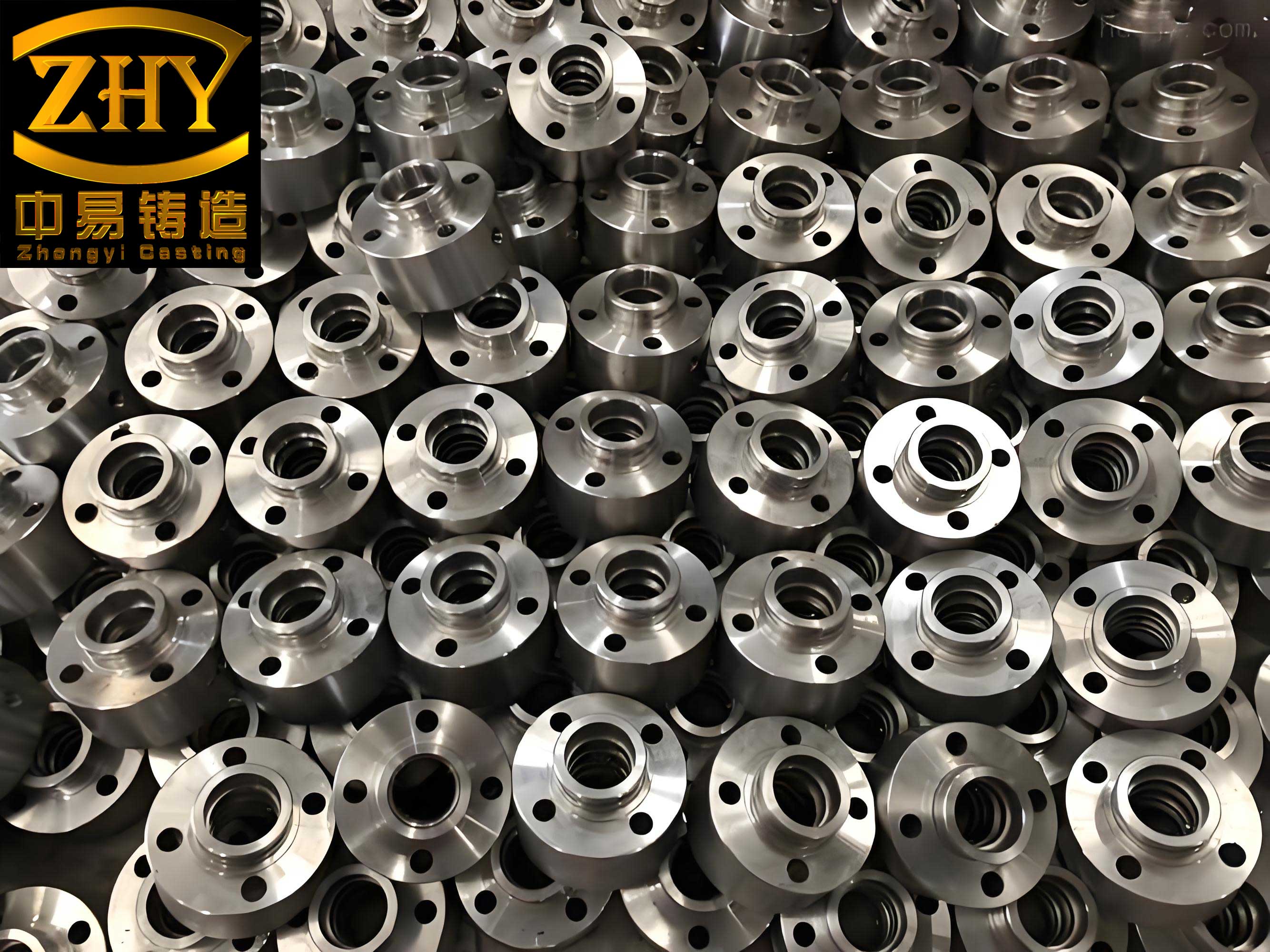
The subject of this study was a hydraulic valve body shell manufactured from grade QT500-7 nodular cast iron. The casting had a complex geometry with varying wall thicknesses, integral bosses, and internal oil galleries. The initial production process employed green sand molding using HWS high-pressure squeeze lines, with four castings arranged in a single mold. Melting was done in an electric furnace, followed by nodularization using a wire-feeding method. The initial pouring temperature was set between 1360°C and 1380°C. Feeding was attempted using KL61 exothermic sleeves as risers. Despite this standard setup, the reject rate due to shrinkage porosity exceeded 30%, manifesting as surface sinks, internal shrinkage in boss areas, and leaks in high-pressure oil passages after machining and testing.
To systematically diagnose the problem, I employed computational simulation using MAGMAsoft and conducted multiple experimental batches. The simulation results clearly identified critical risk zones. The areas of concern were primarily the top feeding points and the side walls where the oil galleries were machined. These zones corresponded to the last regions to solidify, acting as thermal centers or “hot spots.” A summary of the initial process parameters and the observed defect locations is presented in Table 1.
| Process Parameter | Initial Value/Range | Primary Associated Defect Location |
|---|---|---|
| Carbon Equivalent (CE) | ~4.5% | Generalized micro-porosity |
| Pouring Temperature | 1360 – 1380 °C | Top riser neck shrinkage, macro-porosity |
| Riser Type (Thermal Modulus) | KL61 (≈1.6 cm) | Shrinkage cavity beneath riser |
| Local Geometry | Side wall thickness transition | Subsurface porosity in oil gallery region |
My analysis pinpointed four interconnected root causes for the pervasive shrinkage porosity in this nodular cast iron shell:
1. Suboptimal Carbon Equivalent: The initial iron chemistry aimed for a CE of around 4.5%. While within an acceptable range, it was at the lower end for maximizing graphite expansion. The self-feeding capability of nodular cast iron is highly sensitive to CE. At lower CE values, the volume of graphite precipitated decreases, reducing the compensatory expansion. This can be conceptualized by modifying the expansion term in our volume change model. The expansion due to graphite is proportional to the carbon content available for nodule formation. If the total carbon is low, even with full nodularization, the expansion pressure may be insufficient to counteract the solidification shrinkage of the austenite matrix. The relationship between shrinkage porosity risk (SPR) and CE can be empirically modeled for a given section size:
$$ SPR \propto \frac{1}{(CE – CE_{critical})^n} $$
where $CE_{critical}$ is a threshold value below which shrinkage risk increases dramatically, and $n$ is an exponent derived from experimental data. For this specific casting geometry, our data suggested $CE_{critical}$ was approximately 4.5%.
2. Excessive Pouring Temperature: A high pouring temperature, while ensuring good mold filling and reducing mistrun risks, has a double-edged effect on shrinkage in nodular cast iron. Firstly, it increases the total liquid contraction ($\Delta V_{liquid}$) as the metal cools from a higher temperature to the liquidus. Secondly, it delays the start of solidification, potentially causing the riser to lose thermal efficiency before the critical sections have solidified. The thermal gradient between the casting and the riser diminishes faster. The ideal pouring temperature is a compromise that prevents premature solidification in the gates but minimizes superheat. The thermal energy, Q, that must be removed for solidification is:
$$ Q = m \left[ c_p (T_{pour} – T_{liquidus}) + L_f + c_s (T_{solidus} – T_{ambient}) \right] $$
where $m$ is mass, $c_p$ and $c_s$ are specific heats of liquid and solid, $L_f$ is latent heat of fusion, and $T$ are temperatures. A higher $T_{pour}$ directly increases the first term, extending the solidification time and requiring more effective feeding.
3. Inadequate Riser Feeding Capacity: The KL61 exothermic riser, with a thermal modulus of 1.6 cm, was theoretically sized based on general rules. However, the modulus calculation must account for the dynamic solidification of nodular cast iron. The riser’s effectiveness depends on its ability to remain liquid and under pressure (from expansion) longer than the casting section it feeds. The required riser modulus $M_r$ can be estimated using Chvorinov’s rule, considering the feeding demand:
$$ M_r \geq k \cdot M_c $$
where $M_c$ is the modulus of the casting hot spot, and $k$ is a safety factor greater than 1 (typically 1.1-1.2 for nodular cast iron with exothermic risers). Our initial design likely had a $k$ value too close to 1, failing to provide a sufficient safety margin. The visual shrinkage cavity directly under the riser was a clear indicator of premature riser solidification.
4. Unmitigated Local Hot Spots: The casting geometry featured a thickened side wall section that fed into the region where the high-pressure oil passage was machined. This created a localized thermal center. In the absence of external chilling, this region solidified last, creating an isolated liquid pool cut off from the feeding network. The solidification time $t$ for a simple shape is given by Chvorinov’s rule:
$$ t = B \left( \frac{V}{A} \right)^2 = B \cdot M^2 $$
where $B$ is the mold constant, $V$ is volume, $A$ is surface area, and $M$ is the geometric modulus ($V/A$). The side wall junction had a significantly higher modulus than the surrounding walls, leading to a longer solidification time $t$. Without directional solidification towards a riser, this area became susceptible to shrinkage porosity.
Based on this multifaceted analysis, I devised and implemented a comprehensive set of corrective actions. The goal was to enhance the innate self-feeding ability of the nodular cast iron and to actively control the solidification pattern.
Action 1: Optimizing Iron Chemistry for Maximum Graphite Expansion. I adjusted the base iron chemistry to increase the carbon content. The target for the raw iron in the furnace was raised to 3.80-3.85% carbon. After nodularization treatment via wire feeding, the final carbon equivalent was tightly controlled within the range of 4.55% to 4.65%. This shift placed the iron chemistry closer to the eutectic peak, maximizing the volume fraction of graphite nodules and the associated expansion pressure. The change in expansion potential can be approximated by considering the difference in carbon content available for graphite formation. If we assume all excess carbon above the solubility in austenite forms graphite, the volumetric expansion $\Delta V_g$ is roughly proportional to the weight percent of graphite, $W_{Gr}$:
$$ \Delta V_g \approx \alpha \cdot W_{Gr} \cdot \rho_{Fe}^{-1} $$
where $\alpha$ is a conversion factor related to the density difference between graphite and the iron matrix, and $\rho_{Fe}$ is the density of iron. Increasing carbon content directly increases $W_{Gr}$, thereby boosting $\Delta V_g$.
Action 2: Strategic Reduction of Pouring Temperature. I lowered the pouring temperature range to 1340-1350°C. This required meticulous coordination of the melting and treatment process to prevent nodularization fade. The practice involved precise control of tapping temperature, wire-feeding temperature, and minimizing hold time before pouring. The reduction in superheat decreased the total heat content, shortening the solidification time and reducing the demand on the feeding system. The comparative thermal analysis is shown in Table 2.
| Parameter | Old Process | New Process | Estimated Effect on Solidification |
|---|---|---|---|
| Pouring Temp. (Tp) | 1370 °C (avg) | 1345 °C (avg) | Reduced superheat by ~25°C |
| Liquid Contraction (ΔVliq) | Higher | Lower | Decreased total shrinkage volume |
| Solidification Time (t) | Longer | Shorter | Riser remains effective for a larger fraction of t |
| Thermal Gradient | Shallower | Steeper | Improved directional solidification |
Action 3: Upgrading the Riser System. To address the insufficient feeding capacity, I replaced the KL61 risers with larger KL86 exothermic sleeves, which have a thermal modulus of approximately 1.9 cm. This increase in riser modulus provided a greater reservoir of hot metal and extended its solidification time. Furthermore, I added 2 mm of additional machining allowance on the top surface of the casting at the riser contact point. This served as a “safety cap,” ensuring that any minor pipe shrinkage in the riser neck would be removed during machining, guaranteeing sound material in the final part.
Action 4: Implementation of Conformal Chill Plates. This was the most critical innovation for this specific nodular cast iron shell. To eliminate the isolated hot spot in the side wall, I designed and developed conformal external chill plates. These chills were machined to match exactly the external contour of the problematic wall section. When placed in the mold, they provided intense localized cooling, effectively reducing the thermal modulus of that region and promoting directional solidification towards the main riser-fed sections. The effectiveness of a chill can be quantified by its chilling power, which depends on its material (typically iron or copper), mass, and contact area. The new solidification sequence forced the side wall to solidify before the adjacent sections it was feeding, thereby eliminating the condition for shrinkage porosity formation. A summary of the implemented solutions and their theoretical basis is consolidated in Table 3.
| Corrective Action | Target Parameter | Metallurgical Principle | Key Formula/Relationship |
|---|---|---|---|
| Increase CE to 4.55-4.65% | Graphite Expansion (ΔVg) | Maximize self-feeding via graphite precipitation | $$ CE = \%C + \frac{\%Si}{3};\quad \Delta V_g \propto (CE – CE_0) $$ |
| Reduce Pour Temp to 1340-1350°C | Superheat & Solidification Time (t) | Minimize liquid contraction and shorten feeding demand window | $$ Q_{superheat} = m c_p (T_p – T_{liq}); \quad t \propto Q_{total} $$ |
| Use KL86 Risers (M=1.9 cm) | Riser Modulus (Mr) | Ensure riser solidifies after casting hot spot (Mr > Mc) | $$ M_r = \frac{V_r}{A_r}; \quad M_r \geq 1.1 \cdot M_c $$ |
| Apply Conformal External Chills | Local Modulus (Mlocal) | Eliminate thermal centers, enforce directional solidification | $$ t_{chilled} = B \cdot (M_{local}^2 / \beta); \quad \beta > 1 $$ |
The implementation of this integrated approach required careful process control. For the chills, a specific protocol was established: they were coated with a refractory wash and thoroughly dried to prevent metal-chill welding and the generation of gas defects. The modified process was subjected to extensive trial runs. The results were definitive. Visual inspection of the castings showed no surface sinks or shrinkage cavities. Destructive sectioning of sample castings through the previously problematic oil gallery regions revealed dense, sound metal with no subsurface porosity. Most importantly, in subsequent customer processing, the rate of leaks during pressure testing after machining fell to zero. The corrective actions successfully transformed a process with a 30% rejection rate into a robust, production-worthy system for manufacturing high-integrity nodular cast iron shells.
This case study underscores several critical principles for producing sound nodular cast iron castings, especially complex ones like shells. First, the iron chemistry must be viewed not just as a mechanical property target but as a fundamental process variable controlling solidification soundness. Leveraging the carbon equivalent to enhance the natural graphite expansion is paramount. Second, thermal management is a holistic endeavor. It involves balancing pouring temperature to minimize drawbacks, designing risers with ample safety margins to account for the dynamic solidification of nodular cast iron, and actively manipulating thermal gradients through chills. Conformal chills represent a powerful tool for addressing localized hot spots in complex geometries where adding risers is impractical. Their design and application require precision but yield exceptional results in eliminating shrinkage porosity.
In conclusion, solving shrinkage porosity in nodular cast iron components is a multidimensional challenge that demands a systematic approach combining metallurgical knowledge, thermal analysis, and practical foundry engineering. By understanding and harnessing the unique solidification characteristics of nodular cast iron—particularly its graphite expansion—and by proactively controlling the cooling process through optimized risering and strategic chilling, it is possible to achieve defect-free castings even in demanding applications. The success with this shell casting validates that a deep dive into the root causes, supported by simulation and empirical data, can lead to effective, reliable solutions that ensure quality and profitability in nodular cast iron production. The journey from persistent defect to robust process reaffirms the importance of a scientific methodology in the art and science of metal casting.