
The production of heavy, high-strength gray iron castings presents a formidable challenge in foundry engineering. One quintessential example is a large bearing housing used in critical energy and drainage systems. Demanding a material grade of HT300 (akin to ASTM Class 40 or higher), this component is characterized by extreme variations in wall thickness. The main body features walls of 80 mm, transitioning to a minimal section of 30 mm, while the massive base plate measures a substantial 250 mm in thickness. With a final weight exceeding 4000 kg, the casting must be entirely free from defects such as shrinkage cavities, porosity, cracks, and sand inclusions. The inherent difficulty lies in managing the solidification and feeding of such a gray iron casting with disproportionate geometry, where the thick base acts as a significant thermal mass demanding precise control to prevent internal shrinkage.
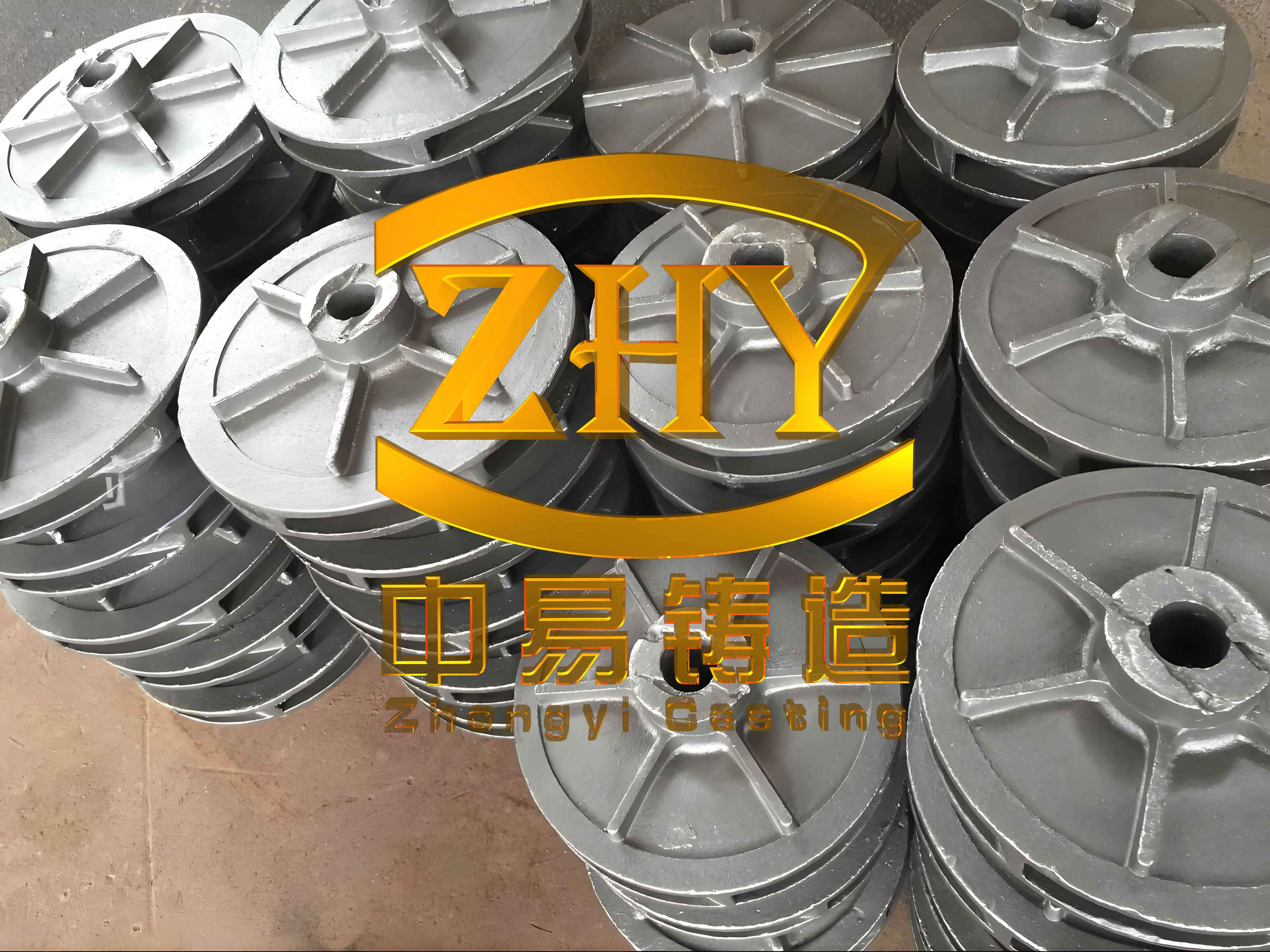
The structural nature of such components predisposes them to specific failure modes. Firstly, the severe thermal gradients created during cooling between thin and thick sections generate immense casting stresses, promoting hot tears or cracks, particularly at fillets and junctions. Secondly, and most critically, the massive base plate solidifies last, creating an isolated thermal hot spot. The long liquid-to-solid feeding path and the significant volume of liquid metal required to compensate for contraction often exceed the capability of conventional gating and risering systems, leading to macro-shrinkage cavities. Thirdly, the slow cooling in the thick section can deteriorate the microstructure, promoting the formation of coarse, type D or E graphite flakes and reducing the mechanical properties locally, which is unacceptable for a high-strength gray iron casting. The key machining surfaces, primarily the inner bore and the bearing seat face, add another layer of complexity as they must be sound and dense.
Initial Foundry Practice and Resultant Defects
The initial manufacturing approach utilized hand molding with resin-bonded sand. To prioritize the surface quality of critical machining areas, the casting was positioned with its heavy base plate at the bottom (drag) and the bearing seat on the side. The parting line was set at the top surface of the base. A pressurized gating system was employed, with a ratio of sprue: runner: ingate cross-sectional areas set at 1:1.8:0.85. Iron was introduced from the side at two levels. To accelerate cooling, chills were placed against the thick base plate. Supplementing feeding, several small neck-down (or “duck-bill”) risers were positioned on the top surface. The melt chemistry and key process parameters are summarized in Table 1.
| Parameter | Value / Composition (wt.%) |
|---|---|
| Carbon (C) | 3.1% |
| Silicon (Si) | 1.68% |
| Manganese (Mn) | 0.86% |
| Phosphorus (P) | 0.028% |
| Sulfur (S) | 0.007% |
| Copper (Cu) | 0.45% |
| C.E. (Carbon Equivalent) | 3.66% |
| Pouring Temperature | 1320 – 1340 °C |
| Riser Type | Duck-bill (Top) |
| Chills | Applied on base plate |
This initial process proved unstable. Out of six castings produced, four were scrapped due to severe shrinkage cavities and associated shrinkage cracks located at the roots of the top risers and in their vicinity. The defect analysis pointed directly to the feeding limitations of the design. Placing the heaviest thermal mass at the bottom created the worst possible scenario for feeding from top risers. The long vertical feeding distance, combined with the early solidification of the thinner sections, isolated the thick base. The risers, though placed above, could not maintain a liquid feed path long enough to compensate for the volumetric contraction of the massive 250mm section. Furthermore, the proximity of the sprue to the casting body created an additional thermal hotspot, exacerbating the localized shrinkage problem. This experience underscored a fundamental principle: for a gray iron casting with drastic section variations, the pouring position must be designed to facilitate directional solidification towards the risers, not away from them.
Comprehensive Root-Cause Analysis: Gray Iron Solidification Dynamics
To develop a robust solution, a deeper understanding of the solidification characteristics of high-strength gray iron is essential. Unlike ductile iron or steel, gray iron benefits from graphitic expansion during the eutectic freeze. However, this expansion is most effective in countering shrinkage when it occurs after the formation of a rigid, interlocking austenite dendrite network that can contain the pressure. In thick sections, where cooling is slow, the mold wall may yield, and the expansion can be less effective at compensating for the initial liquid contraction and interdendritic shrinkage.
The required feeding volume ($V_{feed}$) can be conceptually approximated by considering the liquid shrinkage and the contraction through the eutectic reaction:
$$ V_{feed} \approx V_{casting} \times (\alpha_{l} \Delta T_{l} + \varepsilon_{eutectic}) $$
where $V_{casting}$ is the volume of the thick section, $\alpha_{l}$ is the liquid thermal contraction coefficient, $\Delta T_{l}$ is the temperature drop from pouring to the start of eutectic solidification, and $\varepsilon_{eutectic}$ is the volumetric change associated with the graphite-austenite eutectic formation. For a high-strength, lower carbon equivalent gray iron casting, the graphitic expansion is reduced, increasing the net shrinkage demand.
The feeding distance ($FD$) from a riser is also critical. For a plate-like thick section, a simplified model is:
$$ FD \approx K \times T $$
where $T$ is the plate thickness and $K$ is a factor dependent on alloy properties and cooling conditions. In the initial design, the effective feeding distance from the top risers to the center of the bottom plate far exceeded any practical $K$ factor for this grade of iron. Additionally, the modulus (Volume/Surface Area) of the thick base ($M_{base}$) is much larger than that of the riser neck ($M_{neck}$). For effective feeding, the riser must solidify last, requiring $M_{riser} > M_{casting}$. The initial small duck-bill risers failed this criterion relative to the massive base section modulus. The problem was therefore systemic: incorrect orientation, inadequate riser modulus, and excessive feeding distance.
Systematic Process Redesign and MAGMA Simulation
The overhaul of the process was methodical, addressing each identified flaw from first principles.
1. Pouring Position Reversal: The most critical change was rotating the casting 180 degrees. The thick base plate was now positioned at the top (cope). This simple but transformative step placed the heaviest thermal mass directly beneath the risers, enabling gravity-fed, directional solidification from the thin sections (now at the bottom) towards the thick section and finally into the risers located above it. This is paramount for a successful gray iron casting of this nature.
2. Gating System Relocation and Optimization: The sprue was moved approximately 200 mm away from the casting body to eliminate its thermal impact. The gating system remained pressurized but was recalibrated to a ratio of 1:1.5:0.85 (sprue:runner:ingate) to ensure proper filling and minimal turbulence. The ingates were positioned to introduce metal at the bearing seat side wall, promoting temperature stratification favorable to directional solidification.
3. Enhanced Cooling and Metallurgical Adjustment: Direct chills over 120 mm thick were placed on the top surface (the machining face of the base plate). This served a dual purpose: (a) significantly increasing the cooling rate of the thick section to refine the graphite structure and prevent carbide formation, and (b) helping to establish a more defined solidification front. The pouring temperature was lowered to 1300-1320 °C, as the thin sections filling first no longer risked cold shuts, and a lower temperature reduces total liquid contraction. The melt chemistry was adjusted to increase the carbon equivalent and copper content, improving both fluidity and the graphitization potential to better utilize expansion, as shown in Table 2.
| Parameter | Optimized Value / Composition (wt.%) | Purpose of Change |
|---|---|---|
| Carbon Equivalent (C.E.) | 3.85% | Increase fluidity & graphitic expansion |
| Copper (Cu) | 0.58% | Enhance strength and pearlite formation |
| Pouring Temperature | 1300 – 1320 °C | Reduce liquid shrinkage volume |
| Base Plate Position | Top (Cope) | Enable directional solidification towards risers |
| Chill Thickness | >120 mm | Accelerate solidification, refine microstructure |
4. Riser Strategy Evolution via Simulation: The initial revised design still used multiple top risers. MAGMA solidification simulation software was employed to virtualize the process. The simulation revealed a persistent risk: the central risers, positioned directly over the hottest spot, created large thermal junctions. While they provided liquid metal, their necks remained liquid too long, creating localized shrinkage at the riser-contact zone (“neck piping”).
The breakthrough came from rethinking the riser type and placement. The central risers were eliminated. Instead, a single, strategically sized “knife-gate” or “pad” feeding riser was placed at the end of the thick base plate farthest from the ingates. This location is naturally cooler and solidifies earlier in the sequence, but the riser design ensures it remains open to feed the long, plate-like section. The remaining risers on the bearing boss sections were retained but with reduced neck dimensions to minimize their thermal contact. This configuration is illustrated in Figure 5a of the original text. The final MAGMA simulation (Figure 5b) confirmed a sound gray iron casting, showing a clear directional solidification pattern ending at the feeder riser, with no isolated liquid pockets or shrinkage predictions.
The success of the simulation-based optimization hinges on accurately modeling the unique behavior of gray iron, including the graphitic expansion. The modified riser design ensures it fulfills its feeding role during the liquid and early eutectic shrinkage phases but is designed to solidify completely before the end of freezing, preventing it from becoming a shrinkage cavity itself. This delicate balance is key to tooling a gray iron casting process.
Production Validation and Final Quality
The optimized process was put into production. The first two castings were produced sound. Subsequently, a batch of 30 castings was manufactured with a 100% yield, demonstrating exceptional process stability and robustness. Machining of the thick base plate and all other critical surfaces revealed dense, defect-free metal. The final mechanical and microstructural properties met the stringent HT300 specifications, as validated by tests on attached coupons, detailed in Table 3.
| Property | Result | Specification/Standard |
|---|---|---|
| Tensile Strength (on attached coupon) | >300 MPa | HT300 Minimum |
| Hardness (HB) | 180 – 210 | As expected for grade |
| Graphite Form | Type A (Flake) | Desirable |
| Graphite Size | Grade 4-5 (ASTM) | Well refined for section |
| Pearlite Content | >90% | Ensures high strength |
| Defect Status (UT/RT) | No shrinkage or porosity | Critical requirement passed |
Universal Principles for Thick-Section Gray Iron Castings
The journey from persistent scrap to consistent success with this heavy gray iron casting yields several universally applicable principles for foundry engineers:
1. Prioritize Feeding Geometry in Pouring Orientation: The casting must be oriented to promote directional solidification from thin to thick sections, culminating at strategically placed risers. This often means positioning the heaviest thermal mass at the top or in direct line with feeders, even if it temporarily complicates molding or requires more elaborate risering.
2. Employ Aggressive Cooling for Microstructure Control: Thick sections in gray iron casting are prone to microstructural degradation. The use of heavy, high-conductivity chills is not merely a suggestion but a necessity to achieve the required graphite morphology and matrix structure, transforming a potential weakness into a sound area.
3. Design Risers to Avoid Creating New Hot Spots: The riser must be a source of liquid metal, not a defect. Its design, location, and neck must ensure it has a higher modulus than the region it feeds while minimizing the thermal mass added at the junction. Edge-fed or pad risers can often be more effective than top risers placed directly over the geometric hot spot for thick-walled gray iron casting components.
4. Leverage Simulation for Iterative Optimization: Numerical simulation tools like MAGMA are indispensable for visualizing solidification sequences, predicting shrinkage risks, and testing “what-if” scenarios without the cost of physical trials. They are particularly valuable for validating the complex interplay between chills, risers, and gating in a gray iron casting process.
5. Integrate Metallurgical and Process Parameters: The solution is never purely geometrical. Pouring temperature and alloy composition (particularly Carbon Equivalent and minor alloys like Copper) must be tuned in conjunction with the mold design. A lower pouring temperature reduces shrinkage demand, while a carefully balanced C.E. ensures adequate fluidity and expansion behavior for the specific geometry of the gray iron casting.
In conclusion, the reliable production of high-integrity, thick-section gray iron casting components demands a holistic approach. It requires moving beyond standard practice to a physics-based design strategy that rigorously applies principles of directional solidification, controlled cooling, and controlled feeding, all verified through modern simulation technology. The bearing housing case study stands as a testament to the fact that even the most challenging geometries can be mastered through systematic analysis and integrated process engineering.