
In my extensive experience in foundry engineering, the application of sand faced permanent iron molding (SFPM) for producing gray iron castings, especially thin-walled components, has revolutionized batch production efficiency and quality. This process combines the durability of metal molds with the flexibility of sand coatings, offering superior dimensional accuracy and surface finish for gray iron castings. Gray iron castings are widely used in industrial applications due to their excellent machinability and damping capacity, but their production for thin-section structures poses significant challenges, such as cold shuts, misruns, and white iron formation. Here, I will delve into the intricacies of SFPM for gray iron castings, focusing on design parameters, operational insights, and theoretical underpinnings, supported by tables and formulas to encapsulate key concepts.
The SFPM process involves creating a permanent iron mold lined with a thin layer of resin-bonded sand, which is cured to form a precise cavity. This method enhances heat dissipation compared to traditional sand casting, leading to faster solidification and finer microstructures in gray iron castings. However, for thin-walled gray iron castings—defined by wall thicknesses as low as 2-3 mm—the rapid cooling can exacerbate defects. From my perspective, the success hinges on meticulous process optimization. For instance, a component like a sanding machine base, with uniform walls of 6 mm and minimal sections of 2.3 mm, demands careful consideration of gating, venting, and coating thickness to ensure flawless gray iron castings.
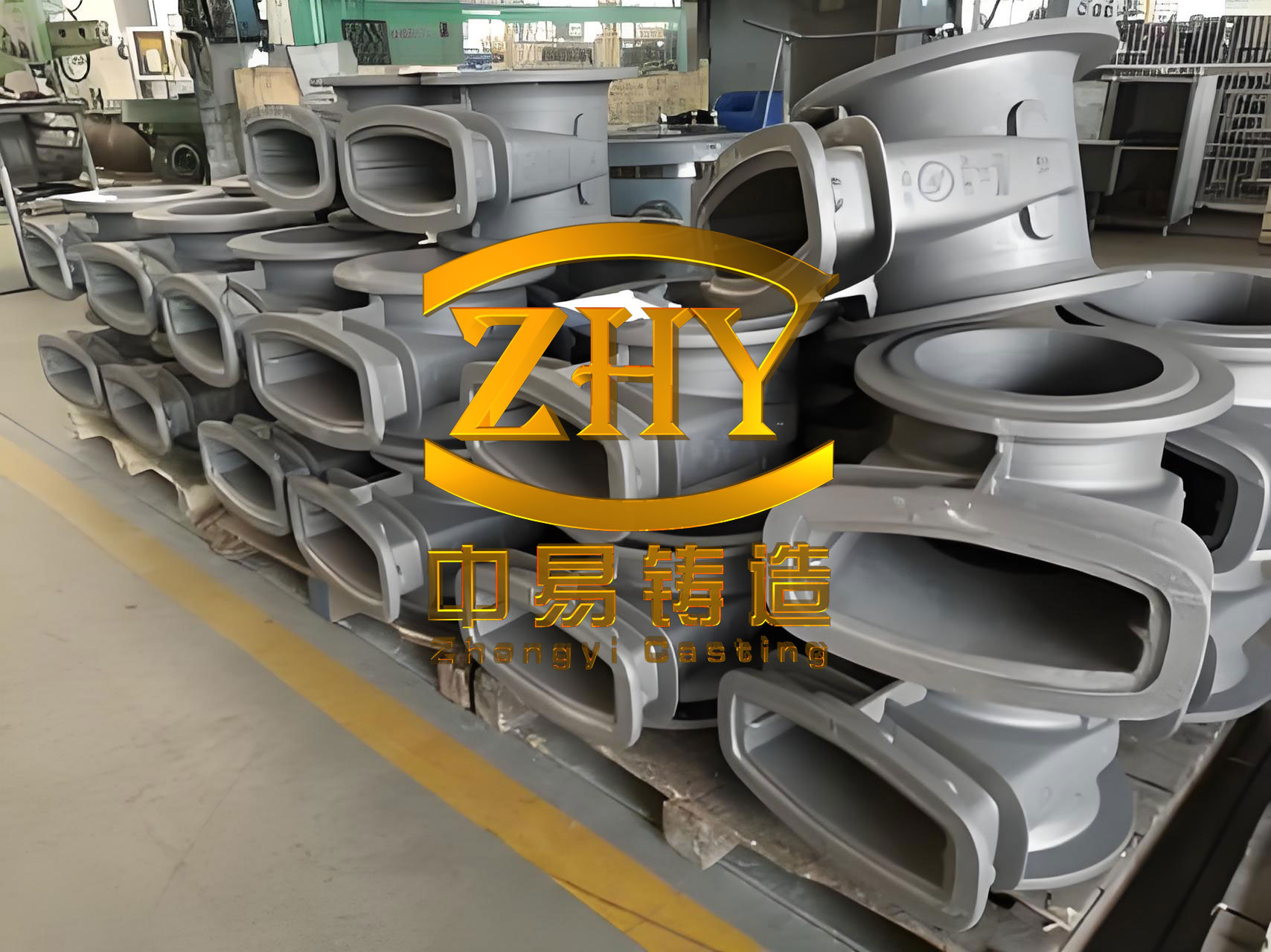
One of the primary difficulties in SFPM for gray iron castings is the structural constraints of thin-walled designs. The part geometry, often resembling a trapezoidal shell, necessitates a single-cavity molding approach without intermediate parting lines, increasing the adhesion force during pattern stripping. Since the sand hardens before demolding, this can lead to damage if not managed properly. Moreover, gray iron castings have lower fluidity compared to ductile iron, compounded by the high thermal conductivity of the iron mold. This accelerates the cooling of the molten metal front, raising risks of incomplete filling and chill formation in critical areas like windows or thin sections. Additionally, the internal iron core restricts contraction during cooling, predisposing gray iron castings to thermal stress and cold cracking. To address these, I emphasize a holistic design strategy that leverages the smooth cavity surface and adjustable sand layer thickness inherent in SFPM.
The gating system is paramount for gray iron castings in SFPM. I recommend a semi-closed system with specific ratios to facilitate rapid filling. For example, using a cross-sectional area ratio of sprue: runner: ingate as 1.2:1.5:1, and increasing the number of ingates, ensures uniform flow and minimizes turbulence. This can be expressed mathematically to optimize fluid dynamics. The flow rate \( Q \) of molten iron into the cavity can be modeled using Bernoulli’s principle with modifications for viscous losses in thin sections:
$$ Q = A \cdot v = \frac{\pi d^2}{4} \cdot \sqrt{\frac{2 \Delta P}{\rho \left(1 + f \frac{L}{D}\right)}} $$
where \( A \) is the cross-sectional area, \( v \) is velocity, \( \Delta P \) is the pressure differential, \( \rho \) is the density of gray iron (approximately 7.2 g/cm³), \( f \) is the friction factor, \( L \) is the flow length, and \( D \) is the hydraulic diameter. For gray iron castings, maintaining a high \( Q \) reduces premature cooling. Venting is equally critical; proper venting prevents gas entrapment and reduces backpressure, which I achieve by integrating micro-porous channels in the sand layer. The gas permeability \( k \) of the sand coating influences this, and it can be approximated for resin-bonded sands:
$$ k = \frac{\phi^3}{c (1-\phi)^2} $$
where \( \phi \) is porosity and \( c \) is a constant dependent on grain size. Using finer sand grains (e.g., AFS 70-100) enhances surface finish and reduces flow resistance, crucial for intricate gray iron castings.
Sand layer and iron mold thickness are adjustable parameters that govern the thermal regime. For thin-walled gray iron castings, I increase the sand layer thickness to 5-20 mm, particularly on internal cores, and reduce the iron mold thickness to 10-25 mm. This balances heat capacity and promotes better yieldability. The thermal analysis can be summarized using Fourier’s law for transient heat conduction during solidification. The temperature gradient \( \nabla T \) in the sand layer affects cooling rate \( R \):
$$ R = \frac{\partial T}{\partial t} = \alpha \nabla^2 T $$
where \( \alpha \) is thermal diffusivity. For gray iron castings, a lower \( R \) in thin sections prevents white iron formation, which is related to the critical cooling rate \( R_c \) for graphite precipitation. Empirical data suggest \( R_c \approx 10-20^\circ \text{C/s} \) for gray iron; thus, adjusting sand thickness modulates \( R \). Table 1 summarizes key design parameters for SFPM in gray iron castings production.
| Parameter | Recommended Range for Gray Iron Castings | Impact on Thin-Walled Components |
|---|---|---|
| Sand Layer Thickness | 5-20 mm | Reduces cooling rate, prevents chilling |
| Iron Mold Thickness | 10-25 mm | Enhances durability while allowing flexibility |
| Gating Ratio (Sprue:Runner:Ingate) | 1.2:1.5:1 | Promotes rapid, laminar filling |
| Sand Grain Size (AFS) | 70-100 | Improves surface finish and reduces friction |
| Pouring Temperature | ≥1320°C | Compensates for fluidity loss in gray iron |
| Venting Porosity | Optimized via micro-channels | Minimizes gas defects in complex geometries |
In practice, operational nuances significantly affect outcomes for gray iron castings. Demolding requires careful timing; I apply release agents or lubricants to critical areas to reduce adhesion, and initiate stripping soon after sand curing to leverage residual plasticity. Pouring practices are vital: preheating the mold to 200-300°C facilitates hot molding, and maintaining pouring temperatures above 1320°C with a fast pour time (around 7 seconds for a typical 7 kg casting) mitigates front-end cooling. The pouring time \( t_p \) can be estimated based on volume \( V \) and flow rate:
$$ t_p = \frac{V}{Q} $$
For gray iron castings, minimizing \( t_p \) is essential to avoid misruns. Early shakeout, within 5-10 minutes after pouring, alleviates constrained contraction and reduces cracking risks. This aligns with the solidification time \( t_s \) calculated via Chvorinov’s rule, modified for SFPM:
$$ t_s = k \left( \frac{V}{A} \right)^n $$
where \( k \) and \( n \) are constants dependent on mold material—for SFPM, \( k \) is lower than in sand molds due to higher cooling capacity, necessitating quicker handling for gray iron castings.
The efficacy of SFPM for gray iron castings is evident in production metrics. In batch runs exceeding tens of thousands of units, I’ve observed yield rates up to 89%, with scrap rates below 2%, and an iron-to-sand ratio as low as 1:1. This underscores the material and energy savings. Table 2 compares SFPM with conventional sand casting for gray iron castings, highlighting advantages.
| Aspect | SFPM for Gray Iron Castings | Traditional Sand Casting for Gray Iron Castings |
|---|---|---|
| Surface Finish | Excellent, near-net-shape | Moderate, often requires machining |
| Dimensional Tolerance | Meets CT8 per GB6414-86 | Typically CT9-CT10 |
| Production Rate | High (e.g., 40 pieces/hour) | Lower due to slower cycles |
| Material Utilization | Improved (weight reduction ~22%) | Less efficient |
| Energy Consumption | Reduced via faster cooling | Higher due to longer processing |
| Defect Rate in Thin Walls | Low with optimized parameters | Higher incidence of cold shuts |
From a metallurgical standpoint, the rapid solidification in SFPM can influence the graphite morphology in gray iron castings. The flake graphite distribution, critical for properties, is governed by cooling rates and inoculation. I often use inoculants like FeSi to promote type A graphite, and the effect can be modeled via nucleation theory. The number of graphite nuclei \( N \) relates to undercooling \( \Delta T \):
$$ N = N_0 \exp\left(-\frac{\Delta G^*}{k_B T}\right) $$
where \( \Delta G^* \) is the activation energy for nucleation, \( k_B \) is Boltzmann’s constant, and \( T \) is temperature. For gray iron castings, controlling \( \Delta T \) through mold design ensures desirable microstructures. Additionally, thermal stress analysis is crucial to prevent cracking. The stress \( \sigma \) during cooling can be approximated using Hooke’s law with thermal strain:
$$ \sigma = E \cdot \alpha_T \cdot \Delta T $$
where \( E \) is Young’s modulus for gray iron (around 100-140 GPa), \( \alpha_T \) is the coefficient of thermal expansion (≈12×10⁻⁶ /°C), and \( \Delta T \) is the temperature gradient. By increasing sand layer thickness, \( \Delta T \) is reduced, lowering \( \sigma \) and enhancing integrity in thin-walled gray iron castings.
In summary, the SFPM process is highly adaptable for gray iron castings, even in demanding thin-section applications. Key to success is an integrated approach: optimizing gating for rapid filling, enhancing venting to eliminate gases, tailoring sand and mold thicknesses for thermal management, and executing precise operational controls. The repeatability of gray iron castings in SFPM makes it ideal for high-volume orders, with benefits extending to resource conservation and cost reduction. Future advancements could involve simulation software for virtual trials, but the core principles remain grounded in understanding the interplay between fluid dynamics, heat transfer, and material science for gray iron castings. Through continuous refinement, SFPM solidifies its role as a cornerstone in modern foundry practices for producing high-quality gray iron castings.