
The reliability and longevity of braking systems in commercial vehicles are paramount to operational safety. A critical component within this system, the brake drum, is predominantly manufactured from gray cast iron due to its favorable combination of properties. However, a persistent challenge faced by these gray iron castings is their susceptibility to thermal fatigue cracking under the severe service conditions of repeated braking cycles, which involve intense and rapid heating followed by cooling.
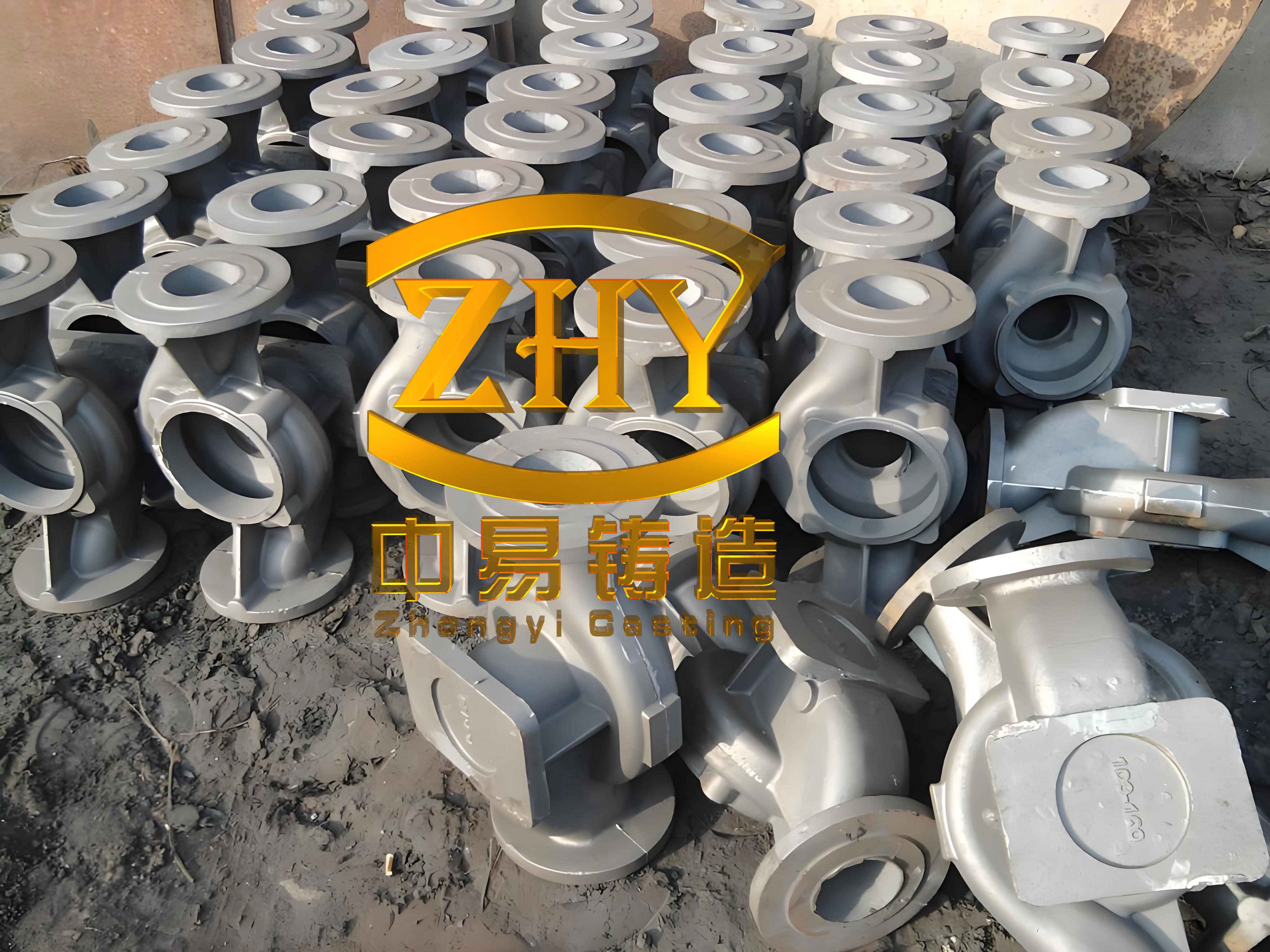
Gray iron castings are indispensable Fe-C-Si multicomponent alloys in industry, prized for their excellent wear resistance, damping capacity, machinability, and crucially for this application, good thermal conductivity. The performance and service life of these castings are fundamentally governed by their microstructure, specifically the morphology of the graphite flakes and the metallic matrix. While higher carbon equivalent (CE) values improve castability and thermal properties, they typically lead to a higher volume fraction of graphite, which can reduce mechanical strength if the graphite morphology is not controlled. The sharp, pointed ends of conventional flake graphite act as potent stress concentrators, initiating micro-cracks under thermal or mechanical load and ultimately leading to premature failure. This investigation focuses on a metallurgical strategy to enhance the performance of high-carbon-equivalent gray iron castings by modifying the graphite morphology itself, a process termed graphite end passivation.
1. The Concept of Graphite Passivation in Gray Iron Castings
1.1 Definition and Significance
In standard gray iron castings, graphite precipitates as interconnected flakes with sharp, acicular tips. Graphite possesses very low mechanical strength (approximately 20 MPa), meaning these flakes effectively behave as internal notches or micro-cracks within the stronger metallic matrix. Under stress, particularly the complex thermo-mechanical stresses in a brake drum, these sharp tips become sites of extreme stress concentration, facilitating crack initiation and propagation.
Graphite passivation refers to a controlled modification of the solidification process whereby the growth of these graphite flakes is influenced to produce a more rounded, blunt-ended morphology. The objective is to transform the graphite from a sharp, crack-initiating feature into a more benign, stress-relieving one. This significantly reduces the stress concentration factor at the graphite tips, thereby enhancing both the conventional mechanical strength and, more importantly, the thermal fatigue resistance of the gray iron castings.
1.2 Classification of Passivated Graphite Morphology
The effectiveness of the passivation treatment can be categorized by examining the resulting graphite shapes under a microscope. The morphology is classified into four distinct types, as summarized in the table below.
| Type | Morphological Description | Passivation Status |
|---|---|---|
| Type I | Graphite flakes with both ends fully rounded/blunted. The flakes are short and stout with a low aspect ratio (length/width). | Fully Passivated |
| Type II | Graphite flakes with both ends rounded/blunted, but with a higher aspect ratio compared to Type I. | |
| Type III | Graphite flakes with one end rounded and the opposite end remaining sharp or pointed. | Partially Passivated |
| Type IV | Graphite flakes with both ends sharp and pointed; typical of non-treated gray iron castings. |
1.3 Quantitative Assessment of Passivation Rate
To objectively evaluate the success of the treatment, a quantitative metric called the “Graphite Passivation Rate” is defined. The assessment is performed on a polished (unetched) sample at 200x magnification. Graphite flakes intersecting the field-of-view boundary and very small flakes (under 50 µm in actual length) are excluded from the count.
The passivation rate is calculated as the percentage of “effective” passivated graphite count relative to the total graphite count in the observed field. Type I and Type II flakes contribute fully to this count, while Type III flakes contribute only 50%, acknowledging their partial passivation. Type IV flakes contribute zero. The formula for calculating the passivation rate (PR) in a given field is:
$$ PR = \frac{N_{I} + N_{II} + 0.5 \times N_{III}}{N_{total}} \times 100\% $$
where:
$$ N_{I}, N_{II}, N_{III} $$ are the counts of Type I, II, and III graphite flakes, respectively, and
$$ N_{total} = N_{I} + N_{II} + N_{III} + N_{IV} $$ is the total number of graphite flakes counted.
For a reliable evaluation of a production batch of gray iron castings, the passivation rate is determined as the average from at least five randomly selected fields on a representative sample.
2. Methodology for Developing Passivated Gray Iron Castings
2.1 Target Component and Material Design Philosophy
The study was centered on a commercial vehicle brake drum, a classic example of a demanding application for gray iron castings. The goal was to develop a material with a high carbon equivalent (CE ≥ 3.9%) to preserve excellent castability, thermal conductivity, and damping properties, while simultaneously overcoming the associated strength penalty through graphite morphology control.
The core strategy involved the synergistic use of two key elements: Rare Earth (RE) and Nitrogen (N).
- Rare Earth Elements: When added in controlled amounts (typically < 0.1%), RE elements act as powerful modifiers. They react with sulfur and oxygen, purifying the melt. More importantly, they adsorb at the growing interface of the graphite, altering the interfacial energies. This promotes growth via a spiral dislocation mechanism along the basal plane, leading to finer, more curved graphite with blunter ends. Furthermore, RE elements refine the pearlitic matrix, increasing the number of grain boundaries which impede dislocation movement, thereby strengthening the metal lattice itself.
- Nitrogen: Nitrogen plays a complementary role. During solidification, nitrogen atoms are adsorbed at the advancing front of the graphite flakes and are also soluble in graphite. This adsorption impedes the lateral growth of the graphite crystals, reducing their aspect ratio, increasing branching, and promoting curvature and tip blunting. Nitrogen also acts as a pearlite stabilizer and refiner. However, its concentration window is critical: an optimal range (e.g., 90-120 ppm) is beneficial, while excessive nitrogen leads to gas porosity (nitrogen blowholes) in the final gray iron castings, rendering them defective.
The hypothesis was that a combined addition of RE (via a cored wire) and N (via a nitrogen carrier like manganese nitride), followed by effective inoculation, would yield a superior microstructure in high-CE gray iron castings.
2.2 Production Process and Experimental Matrix
The trials were conducted under industrial production conditions. The base iron was melted in a medium-frequency induction furnace using a charge of steel scrap and recarburizer. The target base chemistry for the liquid iron prior to treatment is shown below.
| Element | Target Range (wt.%) |
|---|---|
| C | 3.40 – 3.50 |
| Si | 1.10 – 1.30 |
| Mn | 0.55 – 0.75 |
| S | 0.06 – 0.12 |
| P | ≤ 0.05 |
| Cr | 0.3 – 0.6 |
| Cu | 0.4 – 0.6 |
The treatment process sequence was as follows:
- Melting & Tapping: The iron was tapped at 1520-1540°C into a treatment ladle holding 1500 kg.
- Nitrogen Addition: Immediately after tapping, manganese nitride (MnN) was added to the ladle via a plunge method.
- Wire Feeding (Passivation & Inoculation): A cored wire containing RE elements, along with other inoculating elements like Si, Ca, Ba, and Al, was injected into the ladle using an automated wire feeder system. This combined step aimed at simultaneous graphitization control and inoculation.
- Post-Inoculation: The iron was transferred to a pouring ladle, where a final addition of a ferrosilicon-based inoculant (0.7% addition) was made to combat fading effects.
- Casting: The treated iron was poured on a high-pressure molding line into molds configured for two brake drums per mold. The pouring temperature was maintained between 1400-1420°C, with a mold inoculant added during the pour to maintain metallurgical consistency.
To map the effects of RE and N, five separate ladle treatments were performed with varying addition levels, as designed in the experimental matrix. The corresponding final chemical compositions, including the residual RE and N levels, are critical for analysis.
| Sample ID | RE Wire Add. (wt.%) | MnN Add. (wt.%) | Final Chemical Composition (wt.%) | ||||||||
|---|---|---|---|---|---|---|---|---|---|---|---|
| C | Si | Mn | P | S | Cr | Cu | RE | N (ppm) | |||
| 1# | 0.20 | 0.10 | 3.42 | 1.79 | 0.76 | 0.023 | 0.010 | 0.44 | 0.46 | 0.016 | 78 |
| 2# | 0.30 | 0.20 | 3.42 | 1.81 | 0.83 | 0.023 | 0.011 | 0.45 | 0.46 | 0.024 | 96 |
| 3# | 0.40 | 0.30 | 3.41 | 1.83 | 0.90 | 0.022 | 0.010 | 0.46 | 0.458 | 0.033 | 114 |
| 4# | 0.50 | 0.35 | 3.42 | 1.85 | 1.01 | 0.023 | 0.0098 | 0.45 | 0.46 | 0.042 | 120 |
| 5# | 0.60 | 0.40 | 3.41 | 1.86 | 1.04 | 0.022 | 0.010 | 0.44 | 0.46 | 0.053 | 132 |
The carbon equivalent (CE) for all samples, calculated using the formula $$ CE = C + \frac{Si + P}{3} $$, was in the range of 4.0 to 4.1, classifying them as high-carbon-equivalent gray iron castings.
2.3 Evaluation Methods
Samples for testing were extracted from the critical sections of the cast brake drums (e.g., the braking surface and the flange).
- Tensile Strength: Measured on standard Φ10 mm specimens according to ASTM/ISO standards using a universal testing machine.
- Hardness: Brinell hardness (HBW) tests were conducted on prepared surfaces.
- Metallography: Samples were ground, polished, and examined under an optical microscope both in the as-polished state (for graphite morphology and passivation rate calculation) and after etching with nital (to reveal the pearlitic matrix structure).
3. Results, Analysis, and Discussion
3.1 Mechanical Property Evolution
The measured tensile strength and hardness for the five experimental gray iron castings are tabulated below, clearly showing the impact of the RE/N treatment.
| Sample ID | RE Wire / MnN Addition | Tensile Strength (MPa) | Brinell Hardness (HBW) |
|---|---|---|---|
| 1# | 0.20% / 0.10% | 239 | 195 |
| 2# | 0.30% / 0.20% | 263 | 202 |
| 3# | 0.40% / 0.30% | 284 | 213 |
| 4# | 0.50% / 0.35% | 292 | 223 |
| 5# | 0.60% / 0.40% | 280 | 200 |
The data reveals a distinct trend. As the addition of RE and N increases from Sample 1# to Sample 4#, both tensile strength and hardness show a consistent and significant improvement. This can be attributed to the dual effect of matrix refinement and, as will be shown, graphite tip blunting. The strengthening effect can be conceptually related to the Hall-Petch relationship for the refined pearlite colonies and the drastic reduction in stress concentration factor (Kt) at the graphite tips. While the classic Griffith crack theory for brittle materials provides an overarching framework, the improvement in gray iron castings is more directly linked to the reduced severity of the graphite as internal notches.
The peak performance is achieved at the treatment level of Sample 4# (0.5% RE wire, 0.35% MnN). However, a further increase in addition (Sample 5#) leads to a notable decline in both properties. This indicates that an optimal window for treatment has been exceeded.
3.2 Microstructural Transformation and Passivation Rate
The metallographic analysis provides the fundamental explanation for the mechanical property trends. The progression of graphite morphology with increasing treatment intensity is visually clear. In Sample 1#, the graphite remains largely sharp-tipped (Type IV), with only a small fraction showing initial blunting. The calculated passivation rate was approximately 20%. Sample 2# shows increased curvature and a higher proportion of blunted tips (Types II & III), with a passivation rate near 30%.
The most significant morphological improvement is observed in Samples 3# and 4#. The graphite flakes become noticeably shorter, thicker, and more curved. The ends are predominantly rounded. Sample 4# represents the optimum microstructure within this study, achieving a passivation rate of approximately 40%. This direct modification of the graphite geometry is the primary reason for the superior tensile strength, as the stress concentration effect is minimized. The relationship between the stress concentration factor and tip radius (ρ) can be conceptually simplified for an elliptical flaw: $$ K_t \propto \frac{1}{\sqrt{\rho}} $$. Blunting the graphite tip effectively increases ρ, thereby reducing Kt.
Conversely, Sample 5#, with the highest additions, shows a regression in graphite morphology. The flakes appear less refined, and the passivation rate drops back to around 20%. Furthermore, the etched micrographs reveal the state of the metallic matrix. From Samples 1# to 4#, the pearlite becomes progressively finer and more densely packed, contributing to the rising hardness. The eutectic cell size also decreases. In Sample 5#, although some matrix refinement may persist, the overall properties are compromised by other factors.
3.3 The Limits of Treatment and Casting Defects
The decline in properties and microstructure quality in Sample 5# highlights a critical constraint in producing these enhanced gray iron castings. Excessive amounts of RE elements can lead to the formation of high-melting-point rare earth oxysulfides and other compounds, increasing the viscosity of the molten iron. This was empirically observed as poorer fluidity during pouring. High nitrogen levels, especially above the solubility limit in the melt (which is influenced by composition and temperature), result in nitrogen gas pore formation upon solidification.
These phenomena directly explain the results for Sample 5#: reduced fluidity can lead to mist runs and poorer feeding, creating micro-shrinkage or inhomogeneous structures that weaken the casting. The confirmed appearance of subsurface pinholes upon machining in Sample 5# castings is a classic symptom of nitrogen porosity. Therefore, while the goal is to maximize graphite passivation, the process window is bounded by the onset of these detrimental casting defects. The production of high-integrity gray iron castings via this method requires precise control over treatment amounts, pouring temperature, and holding times to avoid crossing these thresholds.
4. Conclusions and Implications for Production of Gray Iron Castings
This investigation demonstrates a viable and effective method for significantly enhancing the performance of high-carbon-equivalent gray iron castings, such as brake drums, through targeted graphite morphology control. The principal conclusions are:
- Synergistic Effect of RE and N: The combined addition of Rare Earth elements (via cored wire) and Nitrogen (via manganese nitride) successfully alters the solidification kinetics of graphite in gray iron castings. This leads to the growth of shorter, curlier graphite flakes with rounded, passivated ends, directly reducing their stress concentration effect.
- Property Optimization: There exists an optimal addition range for these modifiers. Within this window (exemplified by 0.5% RE wire and 0.35% MnN in this study), the graphite passivation rate and the refinement of the pearlitic matrix work in concert to deliver peak mechanical properties. For the tested high-CE iron (CE ~4.05), this resulted in a tensile strength of 292 MPa and a hardness of 223 HBW, representing a substantial improvement over the baseline non-passivated structure.
- Existence of a Process Window: The improvement curve is not monotonic. Exceeding the optimal addition levels leads to a rapid decline in both graphite passivation quality and mechanical properties. This is primarily due to the deterioration of casting properties—increased melt viscosity and the formation of nitrogen-induced gas porosity—which introduce new defects that overwhelm the benefits of microstructure modification.
- Production Technology Requirement: The reliable and consistent production of such passivated gray iron castings necessitates precise process control. This includes accurate weighing and addition of treatment alloys, controlled wire feeding, management of pouring temperature and time to minimize fading, and stringent monitoring of residual element levels (particularly N and RE) to stay within the beneficial window.
The successful implementation of this graphite passivation technology provides a robust pathway for manufacturing high-performance gray iron castings that require an exceptional balance of thermal conductivity, damping capacity, and resistance to thermal fatigue, meeting the escalating demands of modern commercial vehicle braking systems and other severe-service applications.