
In the realm of ferrous foundry engineering, the production of complex, thin-wall castings such as clutch housings or transmission cases represents a significant challenge. These components, characterized by intricate internal geometries, demanding dimensional tolerances, and stringent pressure-tightness requirements, are highly susceptible to a spectrum of casting defects. The pursuit of high yield and consistent quality necessitates a deep, systematic understanding of the root causes of these defects, which often stem from a complex interplay between design, process parameters, and material properties. This article, drawing from extensive practical experience, presents a first-principles analysis of common defects and outlines a methodology for their mitigation, using a specific case study as a foundation for broader principles.
The fundamental challenge lies in managing the physical phenomena inherent to the casting process: turbulent metal flow, heat transfer and solidification dynamics, gas evolution, and the mechanical interaction between molten metal and the mold. Casting defects such as gas porosity, sand inclusions, and core failures are not merely random occurrences but are direct consequences of specific imbalances within this system. A successful casting process is one that is proactively designed to control these phenomena.
Theoretical Foundations of Defect Formation
The formation of major defects can be modeled to guide process design. For instance, the pressure of gas evolving from a core that may lead to porosity is governed by factors including the rate of gas generation and the permeability of the sand and venting paths. The tendency for sand erosion to cause inclusions relates to the velocity and turbulence of the metal stream. We can express some key relationships mathematically.
The pressure buildup in the mold cavity \( P_{gas} \) due to core gas evolution can be considered as:
$$ P_{gas}(t) = \frac{R \cdot G(t) \cdot T}{V_{cavity} \cdot \mu} $$
Where \( R \) is the gas constant, \( G(t) \) is the gas generation rate over time, \( T \) is the temperature, \( V_{cavity} \) is the effective cavity volume, and \( \mu \) is the permeability factor of the venting system. To prevent gas entrapment, \( P_{gas} \) must remain below the metallostatic pressure at the potential defect location and the gas must have a viable escape path before the metal solidifies.
The propensity for mold wall erosion, leading to sand inclusions, is often linked to the dynamic pressure of the flowing metal:
$$ P_{dynamic} = \frac{1}{2} \rho v^2 $$
Where \( \rho \) is the liquid metal density and \( v \) is the local flow velocity. If \( P_{dynamic} \) exceeds the bonding strength of the mold surface at any point, erosion and subsequent casting defects are likely. This underscores the critical importance of gating design to control velocity.
| Defect Type | Primary Mechanism | Key Contributing Factors | Typical Location |
|---|---|---|---|
| Gas Porosity (Blowholes) | Entrapment of gas from cores/mold | High sand binder content, Inadequate venting, Low permeability, High pouring temperature prolonging gas evolution | Upper surfaces, below cores, near internal corners |
| Sand Inclusions | Erosion or collapse of mold/core surface | Low mold hardness, Turbulent metal flow, High velocity gates, Deep mold cavities | Downstream of gates, vertical walls, cope surfaces |
| Core Failure/Shift | Mechanical failure of core under thermal/mechanical load | Insufficient core strength, Inadequate core support (prints), High metallostatic head, Large core mass | Deep, suspended core sections, Core join interfaces |
| Shrinkage Porosity | Inadequate feeding during solidification | Poor riser design, Incorrect thermal gradients, High casting modulus variations | Hot spots, junctions, center of thick sections |
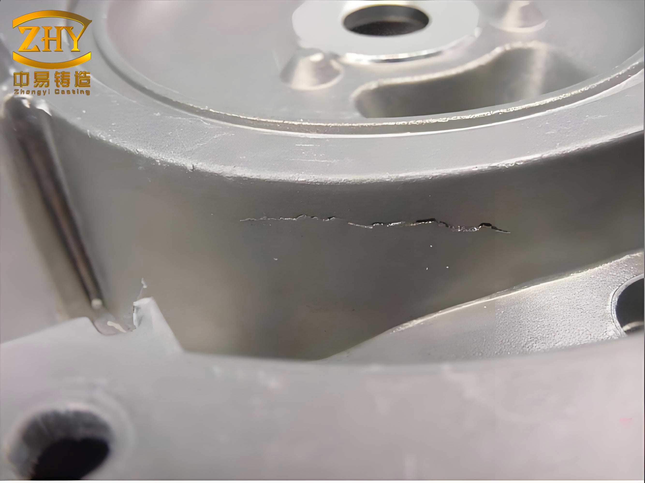
Case Study Analysis: Clutch Housing Production
A pertinent example involves the high-volume production of a clutch housing in Grade HT250. The component is a classic complex thin-wall casting with a minimum wall thickness of 5mm and an intricate internal cavity, requiring pressure tightness. The initial process utilized high-pressure green sand molding with a four-casting mold layout and horizontal gating on the parting line. Despite apparent soundness in initial design, production revealed persistent casting defects.
Defect Manifestation and Initial Hypothesis:
1. Gas Porosity: Consistently appeared at the highest point of the casting’s lower face, directly at the root of an installed vent.
2. Sand Inclusions: Concentrated on the upper flange face near the mold wall.
3. Core Fracture: Occurred at the small connecting prints between two large, mated core assemblies.
Root Cause Investigation:
A systematic analysis moved beyond symptomatic fixes to identify fundamental process flaws.
For the gas porosity, the location was diagnostic. The gas was not from mold moisture (which tends to cause subsurface pinholes) but from the resin-bonded sand cores. The original design shared a single vent passage between two adjacent cores in the multi-cavity mold. This created a bottleneck. The gas generation rate \( G(t) \) from the heated cores overwhelmed the limited vent cross-sectional area \( A_{vent} \), increasing \( P_{gas} \) locally. The gas, seeking escape, accumulated at the last point to solidify—the high point with the vent—and was trapped just beneath the solidified skin, creating a blowhole. The vent itself acted as a chilling rod, solidifying the metal at its root first and blocking the very escape path it was meant to provide.
The sand inclusions on the upper flange were a direct result of process-machine interaction. The vertical face of the flange was formed by the sand mold. In high-pressure molding, corners adjacent to the tooling wall can suffer from “rebound” or lower effective compaction, leading to reduced mold hardness. Measurement confirmed hardness values of 50-60, below the standard 70+ required to resist erosion. The dynamic pressure \( P_{dynamic} \) of the rising metal during fill, combined with potential turbulence, exceeded the low binding strength of this sand area, causing grains to dislodge and become embedded in the casting surface.
The core fracture was a straightforward mechanical failure. The two large cores were essentially cantilevered, joined only by three small-diameter print connections. The core weight and the buoyancy force from the molten iron created a significant bending moment \( M \) at these connection points:
$$ M = F_{buoyancy} \cdot L_{lever} $$
Where \( L_{lever} \) is the distance from the support to the center of mass. The core sand’s tensile strength at the print neck was insufficient to withstand this moment, leading to fracture. This is a critical casting defect as it leads to catastrophic dimensional deviation.
| Defect Type | Identified Root Cause | Principle of Corrective Action | Specific Action Taken |
|---|---|---|---|
| Gas Porosity | Insufficient/Shared core venting capacity leading to localized gas pressure buildup. | Maximize vent cross-sectional area and provide dedicated, shortest path to atmosphere. | Designed independent vent channels for each core, exiting at the absolute highest point of the core package. |
| Sand Inclusions | Low local mold hardness on a vertical wall subject to metal flow. | Eliminate reliance on weak mold areas for critical surfaces. | Redesigned core to extend its print, forming the problematic flange face from the strong core sand instead of the mold sand. |
| Core Fracture | Inadequate bending strength at small, stressed core print connections. | Reinforce the core structure at stress concentration points. | Embedded steel wire rod (core rod) into the small prints during core shooting, effectively creating a reinforced composite structure. |
Systematic Process Improvement Strategy
The corrective actions derived from the root cause analysis embody broader principles for robust process design to eliminate casting defects.
1. Venting System Design Philosophy:
Venting is not an add-on but an integral part of the gating and feeding system. For resin-bonded cores, vents must be:
• Dedicated: Each major core segment should have its own vent path to avoid cross-talk and back-pressure.
• Direct: The path from the gas-generating surface to the atmosphere must be as short and straight as possible.
• Ample: The total vent area should be proportional to the volume and binder content of the core. A rule of thumb is to ensure vent capacity exceeds the peak gas generation rate.
• Terminated Appropriately: Vents should exit into areas that solidify last (e.g., risers) or directly to the atmosphere, not into early-solidifying thin sections.
2. Gating and Mold Fill Analysis:
The goal is to establish a non-turbulent, controlled fill to minimize sand erosion and air entrainment. This often favors systems with lower initial velocities and progressive filling from the bottom up. The use of simulation software to visualize fill patterns, track temperature gradients, and identify potential turbulence zones is now indispensable for preventing flow-related casting defects.
3. Core Engineering and Support:
Cores must be designed as structural components. Key considerations include:
• Print Design: Prints must provide adequate support area and alignment. The bearing pressure \( \sigma_{bearing} \) on the mold print seat should be checked:
$$ \sigma_{bearing} = \frac{W_{core}}{A_{print}} < \sigma_{allowable(mold sand)} $$
• Reinforcement: For long, slender cores or small supporting prints, internal reinforcement with ceramic or steel rods is essential. The rod increases the moment of inertia \( I \) of the cross-section, drastically improving bending resistance.
• Assembly and Sealing: Core assembly joints must be precise. The use of adhesive pastes not only seals gaps but can also contribute to structural integrity if designed to transfer load.
4. Process Parameter Optimization:
Critical parameters must be controlled within a defined window. Pouring temperature is a prime example: too low increases mistrun risk; too high aggravates gas evolution, metal-mold reaction, and shrinkage. The optimal temperature is a compromise that must be found empirically for each casting. Similarly, sand properties (moisture, strength, permeability) require strict statistical process control (SPC).
Broader Implications for Defect Prevention
The lessons extend beyond this specific housing. For any casting prone to casting defects, a holistic view is required. The interaction between the part design, the tooling (pattern and corebox), and the production process must be optimized concurrently. Techniques like Design for Manufacturability (DFM) reviews with foundry engineers at the product design stage can prevent inherently problematic features.
Furthermore, the implementation of real-time monitoring and data analytics is becoming a powerful tool. Tracking process variables (pouring time, temperature, sand properties) and correlating them with defect rates via machine learning models can predict and pre-empt deviations before they result in scrap, transforming defect management from reactive to predictive.
The economic impact of effectively controlling casting defects is profound. It directly increases yield, reduces energy and material waste per good part, minimizes rework and sorting costs, and ensures reliable supply to customers. In high-volume automotive applications, a yield improvement of even a few percentage points translates to substantial annual savings.
Conclusion
Casting defects in complex components are seldom due to a single cause but are the result of systemic process weaknesses. A methodological approach—combining a theoretical understanding of the underlying physics, rigorous root cause analysis of defect patterns, and the disciplined application of sound foundry engineering principles—is paramount for their elimination. The case of the clutch housing demonstrates that solutions often lie not in major technological overhauls but in thoughtful, detailed improvements to core support, venting architecture, and the strategic use of core versus mold to form surfaces. By treating the mold assembly and the metal pour as an integrated, dynamically interacting system, foundries can achieve high-quality, economical production of even the most demanding castings. The continuous refinement of this system through data and analysis represents the future of defect-free casting manufacture.