
In my extensive experience within the foundry industry, the production of reliable, pressure-tight pump body castings remains one of the most challenging tasks. These components are critical in hydraulic and fuel systems, where internal integrity and surface quality are paramount. The occurrence of casting defects during their manufacture is not merely an inconvenience; it is a direct threat to functional performance, operational safety, and production economics. Rejection rates can become economically unsustainable, prompting a deep dive into root cause analysis and systematic improvement. This article synthesizes practical knowledge and engineering principles to explore the nature of common casting defects in pump bodies, their underlying physical causes, and the methodologies—particularly numerical simulation—employed for their diagnosis and elimination.
The pursuit of defect-free castings requires a fundamental understanding of their genesis. Casting defects arise from the complex interplay of metallurgy, fluid flow, heat transfer, and solidification dynamics within the constraints of a specific mold geometry and process parameters. For pump bodies, which often feature complex internal passages created by sand cores, varying wall thicknesses, and integral mounting bosses, the propensity for certain flaws is inherent. The journey from molten metal to sound casting is fraught with potential failure points, each manifesting as a distinct type of defect. A systematic classification is the first step toward effective analysis.
Classification and Morphology of Common Casting Defects
Not all casting defects are created equal. They can be categorized based on their appearance, location, and primary cause. For pump bodies produced via processes like permanent mold or sand casting with metal cores, the following categories are most relevant:
| Defect Category | Specific Defect | Typical Morphology & Location | Primary Cause Domain |
|---|---|---|---|
| Porosity & Cavities | Shrinkage Cavity/Pore | Irregular, dendritic surface. Located in thermal centers (hot spots) like junctions, heavy sections. | Solidification Feeding |
| Gas Porosity (Pinholes) | Small, spherical, shiny-walled holes. Often subsurface or uniformly distributed. | Melt Quality, Mold Gas | |
| Microshrinkage (Sponginess) | Dispersed, interconnected tiny pores. In interdendritic regions of last-to-freeze zones. | Solidification, Alloy Composition | |
| Inclusions & Surface | Sand Inclusions (Sand Hole) | Cavities containing or lined with sand. Often near core surfaces or in areas of turbulent flow. | Mold/Core Integrity, Fluid Dynamics |
| Slag/Dross Inclusions | Non-metallic films or lumps within the metal matrix. | Melt Treatment, Gating System | |
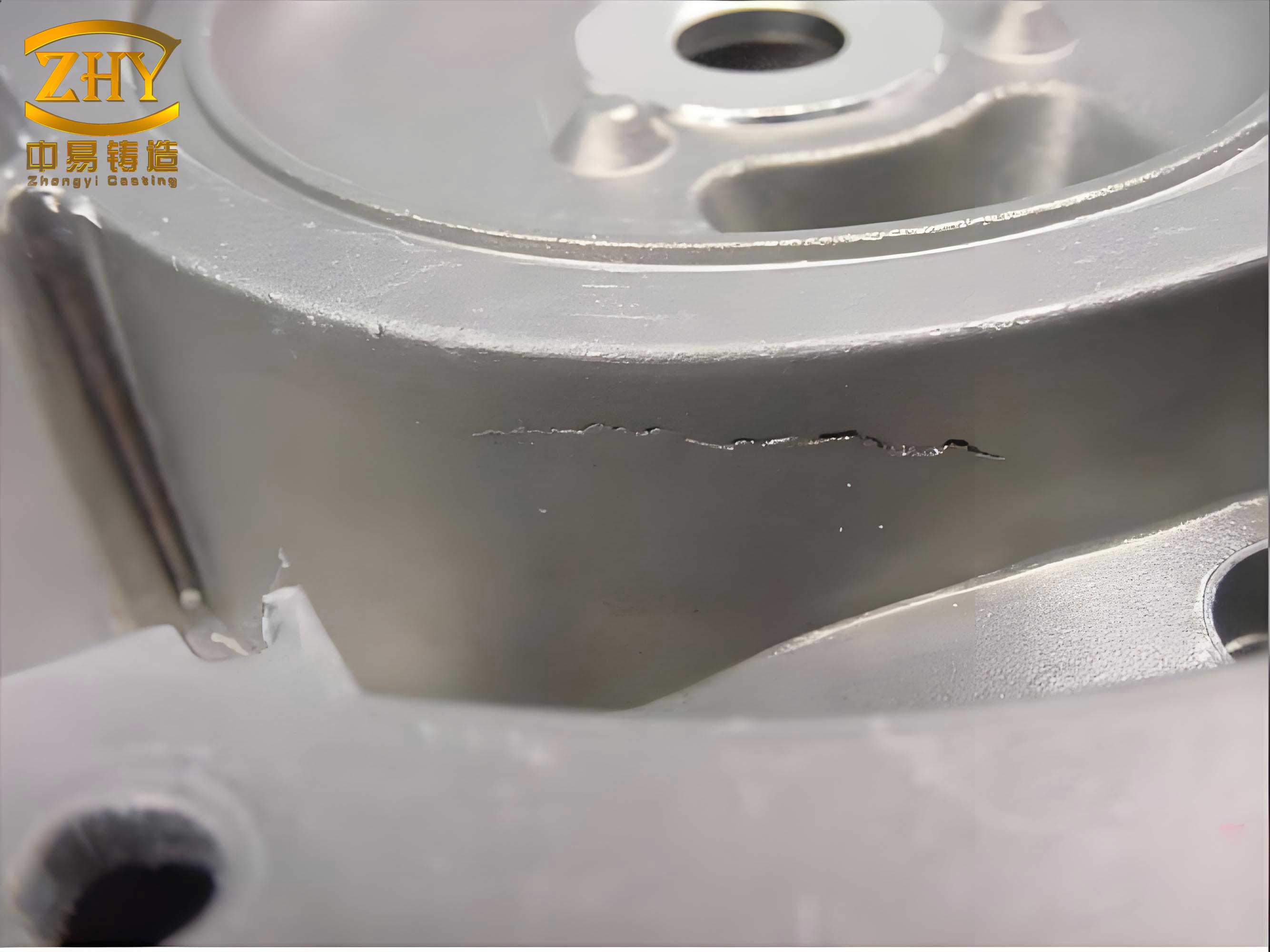
| Shape & Dimension | Distortion, Warping, Hot Tear | Geometric deviation from pattern, cracks (often jagged) in stress-concentrated areas. | Thermal Stress, Mold Restraint |
| Surface | Cold Shut, Misrun | Visible seam or incomplete filling. Low surface finish. | Fluid Flow, Thermal Parameters |
Fundamental Mechanisms Behind Defect Formation
To effectively combat casting defects, one must move beyond mere description and grasp the underlying physical and thermodynamic principles. The formation of major defects can be traced to a few core phenomena.
Solidification Shrinkage and Feeding
Most metals and alloys contract upon solidification. This volumetric change, if not compensated by a continuous feed of liquid metal from a reservoir (a riser or feeder), leads to shrinkage porosity or cavities. The severity is governed by the solidification range and the temperature gradient. For a long freezing-range alloy, microporosity is more likely, while short-freezing alloys tend to form macro shrinkage. The basic requirement to avoid a shrinkage cavity is that the riser must solidify after the casting and provide sufficient feed metal. This can be expressed through Chvorinov’s rule for solidification time:
$$ t = B \left( \frac{V}{A} \right)^n $$
where \( t \) is solidification time, \( V \) is volume, \( A \) is surface area, \( B \) is a mold constant, and \( n \) is an exponent (~2 for sand molds). A riser must have a higher \( V/A \) ratio (modulus) than the section it is feeding.
Fluid Flow and Mold/Core Erosion
The flow of molten metal into the mold cavity is a critical phase. Turbulent flow increases the kinetic energy of the stream, leading to surface oxidation (dross formation) and the erosion of mold or core surfaces, causing sand inclusion casting defects. The Reynolds number (\(Re\)) helps characterize the flow regime:
$$ Re = \frac{\rho v D}{\mu} $$
where \( \rho \) is density, \( v \) is velocity, \( D \) is hydraulic diameter, and \( \mu \) is dynamic viscosity. Maintaining \(Re\) below a critical threshold (typically < 2000 for laminar flow in gating systems) is ideal. Furthermore, abrupt changes in flow direction or cross-section, such as a sharp junction between a riser and the casting, create turbulence and promote defect formation.
Heat Transfer and Thermal Gradients
The pattern of heat extraction determines the solidification sequence. Areas with high thermal mass—where thick sections meet (hot spots)—cool slowest and are prime locations for shrinkage casting defects. The local cooling rate is key and is influenced by the geometry (modulus) and the mold material’s chilling power. The Fourier number (\(Fo\)) can be used to analyze transient heat conduction:
$$ Fo = \frac{\alpha t}{L^2} $$
where \( \alpha \) is thermal diffusivity, \( t \) is time, and \( L \) is a characteristic length. A low \(Fo\) indicates a steep temperature gradient, promoting directional solidification away from the riser, which is desirable.
Influence of Key Process Parameters on Defect Formation
The theoretical principles manifest through controllable process variables. Optimizing these parameters is the practical battlefield against casting defects.
| Process Parameter | Effect on Defects | Optimal Strategy for Pump Bodies |
|---|---|---|
| Pouring Temperature | Too high: excessive gas pickup, mold erosion, coarse grain. Too low: cold shuts, mistruns, poor fluidity. | Use the lowest temperature that ensures complete filling and adequate fluidity for feeding. |
| Pouring Speed/Rate | Too fast: turbulence, sand erosion, gas entrapment. Too slow: premature cooling, cold shuts. | Controlled, smooth filling. Often optimized via simulation to maintain a “critical fill velocity”. |
| Mold & Core Design | Sharp corners create stress risers. Poor gating/risering leads to shrinkage and inclusions. Weak cores break. | Implement fillets, tapered riser connections, optimized runner systems, and robust core prints. |
| Alloy Composition | Freezing range affects shrinkage type. Gas solubility influences porosity. Fluidity affects fillability. | Select alloy for the process (e.g., A356 for good castability). Ensure proper degassing and modification. |
| Cooling Rate | Slow cooling: coarse structure, macro-shrinkage. Fast cooling: fine grain, but high thermal stress. | Use chills (internal or external) to accelerate cooling in hot spots and establish directional solidification. |
Leveraging Simulation for Defect Prediction and Process Optimization
Trial-and-error on the foundry floor is costly and time-consuming. Numerical simulation software, such as ProCAST, MAGMASOFT, or Flow-3D Cast, has become an indispensable tool for predicting and mitigating casting defects before tooling is ever built. These tools solve the fundamental governing equations simultaneously.
- Continuity Equation: $$ \nabla \cdot \vec{v} = 0 $$
- Navier-Stokes Equation (Momentum): $$ \rho \left( \frac{\partial \vec{v}}{\partial t} + \vec{v} \cdot \nabla \vec{v} \right) = -\nabla p + \mu \nabla^2 \vec{v} + \rho \vec{g} $$
- Energy Equation: $$ \rho C_p \left( \frac{\partial T}{\partial t} + \vec{v} \cdot \nabla T \right) = \nabla \cdot (k \nabla T) + \dot{Q} $$ where \( \vec{v} \) is velocity, \( p \) is pressure, \( \rho \) is density, \( \mu \) is viscosity, \( \vec{g} \) is gravity, \( C_p \) is specific heat, \( k \) is thermal conductivity, \( T \) is temperature, and \( \dot{Q} \) is a source term (e.g., latent heat).
The simulation workflow typically involves: 1) Creating a 3D CAD model of the casting, mold, and cores; 2) Meshing the model into finite elements/volumes; 3) Defining material properties and boundary conditions (heat transfer coefficients); 4) Setting process parameters (pour temp, speed, etc.); 5) Running the coupled fluid-flow/thermal/solidification analysis; 6) Post-processing to visualize results.
Key predictive outputs include:
- Solidification Sequence: Animations showing the progression of the solidus front, identifying the last regions to freeze (potential shrinkage zones).
- Shrinkage Porosity/N.R.I. Criteria: Models like the Niyama criterion (\( G/\sqrt{\dot{T}} \), where \( G \) is thermal gradient and \( \dot{T} \) is cooling rate) are calculated at every point to predict regions susceptible to microporosity.
- Fill Pattern & Velocity Vectors: Visualizing how metal enters the cavity, highlighting areas of potential turbulence, air entrapment, or core impingement.
- Temperature Distribution: Identifying hot spots and thermal gradients at critical times during the process.
- Thermal Stress & Distortion: Predicting residual stresses and potential warpage or hot tearing.
A Systematic Case Study: From Defect Analysis to Validated Solution
Consider a typical aluminum alloy pump body cast in a permanent mold with sand cores. The initial process yielded an unacceptable scrap rate due to multiple casting defects.
Initial State & Observed Defects:
- Sand Inclusions (Sand Hole): Appeared as cavities with sand particles on internal passage surfaces. Root causes identified as: 1) Turbulent metal flow at the steep junction between the side riser and the casting body, eroding the core; 2) High pouring speed exacerbating erosion; 3) Insufficient cleaning of loose sand from the core before molding.
- Shrinkage Cavity: A large, irregular cavity was consistently found in a thick bottom mounting boss—a classic thermal hot spot. The solidification sequence showed this region freezing last, isolated from the feeder by thinner, faster-solidifying walls, leading to an unfed shrinkage defect.
- Mechanical Damage (Bumping): Occurred during ejection as the casting fell onto a hard, thin receiving table, damaging fragile fins.
Simulation-Driven Investigation:
A virtual model of the initial design was constructed and analyzed. The fill simulation clearly showed a vortex and high-velocity stream impacting the core near the riser junction. The solidification simulation confirmed the bottom boss as the last point to solidify, with a high predicted Niyama value indicating a high risk for a shrinkage cavity.
Implementing Corrective Actions:
- For Sand Inclusions:
- Design Change: The riser-to-casting junction was redesigned with a gentle slope (increased radius) to ensure smooth, laminar metal transition.
- Process Change: The tilting speed of the pouring furnace was reduced to lower the initial metal velocity.
- Procedure Change: A strict protocol for core blowing and inspection was enforced.
- For Shrinkage Cavity:
- Design Change (Casting Geometry): The problematic bottom boss was redesigned. Its height was reduced, and large fillets were added to its base. This decreased its volume and effective modulus, reducing the size of the thermal hot spot.
- Design Change (Adjacent Wall): The wall adjacent to the boss was slightly thickened. This altered the local solidification dynamics, preventing it from freezing prematurely and “choking off” the feed path from the riser.
- Process Change (Cooling): A high-conductivity chill coating was applied to the mold surface adjacent to the boss to further accelerate its cooling.
- For Mechanical Damage: The receiving table was replaced with a thicker, softer, and more stable material (e.g., a high-temperature polymer composite) to cushion the falling casting.
Validation and Results:
The modified design and process parameters were simulated again. The new fill pattern showed calm, progressive filling. The solidification sequence now clearly showed directional solidification progressing from the bottom boss towards the riser. The Niyama criterion indicated a dramatically reduced risk of shrinkage. Upon implementing these changes in production, the specific sand hole and shrinkage cavity casting defects were eliminated, and mechanical damage was prevented. The overall scrap rate dropped significantly, validating the simulation-based optimization approach.
Comprehensive Strategy for Defect Prevention and Control
Eliminating casting defects is best approached as an integrated system, not a series of isolated fixes. A robust strategy encompasses:
| Strategy Pillar | Key Actions |
|---|---|
| Design for Manufacturability (DFM) | Collaborate with product designers to simplify shapes, avoid abrupt changes, use generous fillets, maintain uniform wall thickness where possible, and design for natural directional solidification. |
| Rigorous Process Control | Standardize and meticulously control all parameters: melting (temperature, degassing), mold/core making (sand properties, coating, curing), pouring (temperature, speed), and cooling (time). Statistical Process Control (SPC) charts are vital. |
| Advanced Melt Treatment | Employ rotary degassing for hydrogen removal, effective filtration in the gating system, and grain refinement/modification treatments appropriate for the alloy. |
| Proactive Simulation | Use casting simulation as a standard step in the tooling design phase. Iterate virtually to optimize the feeding and gating system, riser placement/sizing, and cooling layout before committing to metal patterns. |
| Systematic Quality Inspection | Implement layered inspection: visual, dimensional, pressure testing, and non-destructive testing (NDT) like X-ray radiography or ultrasonic testing for internal casting defects on a sampling or 100% basis. |
Conclusion
The battle against casting defects in critical components like pump bodies is won through a combination of deep scientific understanding and modern engineering tools. Defects such as shrinkage cavities and sand inclusions are not random failures but predictable consequences of violated thermodynamic and fluid dynamic principles. By systematically analyzing these root causes—be it poor feeding logic, turbulent flow, or inadequate thermal management—effective countermeasures can be devised. The advent of high-fidelity numerical simulation has revolutionized this field, allowing engineers to visualize the invisible processes of filling and solidification, predict defect formation with remarkable accuracy, and test improvements in a risk-free digital environment. When this virtual optimization is coupled with disciplined process control and sound foundry practices, the goal of consistent, high-integrity castings becomes fully attainable, driving down costs and enhancing product reliability. The continuous refinement of both simulation accuracy and real-world process knowledge remains the key to further minimizing the impact of casting defects in an ever-more demanding manufacturing landscape.